Engine and power noise

Hi all
I was reading a PDF by Mr J Lange regarding the reduction of electrically generated noise. Before I carry out his suggestions I want to understand exactly how to measure this noise in the first place. I assume I need an oscilloscope. As I would need to buy one so I would appreciate if someone can suggest the specification of an oscilloscope that will allow me to undertake most analysis work on the Ardumower.

Assuming I buy the oscilloscope how do I actually measure the noise generated by the system. What should I measure milli volts, frequency etc and where would I need to attach the probes. Also what readings am I likely to get before noise reduction and after noise reduction.

This is a new area for me so you help will be appreciated.

Lastly which area of the PCB and sensors are affected most by the noise. I can understand that the perimeter coil needs to be located some way away from the motors but what about the IMU and other sensors.

Regards
Max Birley
 
Hi Max,

I didn't know the pdf. Therefore I don't know exactly which noise you want to measure. But I think the noise of the motors?
Measure the signal you want to check without runnig motors and then with running motors.
Good thing to start is to measure the signal behind the coil amplifier and bring the coil then near the motors.
With an Oscilloscope you measure volt over time. When you then see the signal, you can determine the frequency if the signal has a frequency.

Which kind of Oscilloscope you buy depends on your needs. You can buy one, which needs a PC or one that is standalone. All tests I did so far was in a room next to the PC.
I think you don't need to have a very good Osci because there are not very high frequencys to measure in the robot.
Imortant is, that you have two channels and can measure over 30V. This can/must also be done with a 10x probe.

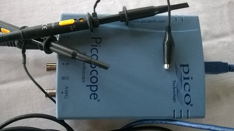
I don't know the following Oscilloscope but I think I would buy me this brand if I would need one. https://www.amazon.de/PicoScope-220...UTF8&qid=1508577268&sr=1-1&keywords=PicoScope
A cheaper one it this: https://www.amazon.de/Hantek-Digita...coding=UTF8&psc=1&refRID=KC9BRER7HVHNBYB9FA40
But I don't know both of them and if they have 10x probes included.
 
Hi Max.
Noise can perturb the receiver coil and the Compass (not the GYRO) of the IMU

For the perimeter Coil.
It's not really easy to manage this problem but put the coil as far as possible from motor,and like Roland say simply test your perimeter reception with and without motor in the center of your mowing area and do the motor Workarround if necessary.

For the Compass.
It's not possible to solve this, If you have a mobile Phone with Compass try to move it near the mower and you are going to see that it's difficult to find the North near the motor.It's why i only use the Gyro and Accel to manage the Direction.

Be carreful that the code i send for GY88 have a bug in the random mowing mode, I solve it and send you with the Ultrasonic sensor.

Oscilloscope i use a PicoScope 2205 and work perfectly to test the Perimeter sender and receiver but can't use it on 24Volt (20V max)

By.
 
Hi Bernard,

the input voltage range is +/-20V with 1:1 probes, but I think it comes with switchable 1:1/10:1 probes.
Do you have a yellow switch (or whatever color) on the probe?

See the pictures where you can see the probes and the comment from Mike Cade and:

https://www.amazon.de/PICOSCOPE-2205-A-2-Kanal-25-MHz-USB-Oszilloskop/dp/B00GZQV246/ref=sr_1_1?ie=UTF8&qid=1508654680&sr=8-1&keywords=PicoScope+2205
 
When I test the Ardumower again I will take some perimeter readings and publish them to get your views on quality
Any suggestions on what is good, acceptable and bad?
Many thanks
Max
 
Hi Roland
I started watching your excellent videos before and got most of the way through them. As they contain so much useful information they can cause an overload for a newbie like me, so I never got to the last few videos. As they are so good I will watch them over again.
It is now obvious I need an oscilloscope to fully understand what is going on with the whole Ardumower system.
I have a logic Analyzer and voltmeter plus a power supply. Do you recommend and other eclectrical test equipment?
Once again many thanks for your great videos.

In the meantime I have a question.
2 months ago I was in the USA using the perimeter sender outside with a power resister and 30 to 50 m of wire. All worked well. Yellow led lights up and Ardumower behaves ok. Now I have returned to the uk and about to start testing the Ardumower and the perimeter wire again. If I connect the same power resister with 1m of wire the sender LED lights up. However if I connect up the whole reel of wire (all the wire 150m - the 50m of wire left in USA) with the 12ohm power resister, the yellow LED flashes once but does not light up and the coil of wire starts to buzzs .
Presumably when I take the wire off the coil and lay it in the garden it will function properly again?
I understand that we are looking to have 1 amp in the perimeter wire.
What is the maximum length of wire for the system. Presumably this is controlled by the max voltage of the system and the resistance of the wire
Presumably the more wire involved in the circuit the higher the voltage needs to be coming out of the DC regulater.
What would the maximum voltage be coming out of the regulater? 24V??

For the 50m of wire layed on the surface I had 12.5 volts and all worked ok.
Why do we waste power with the heating of the power resister?
Many thanks
Max


Max
 
What does a continuously flashing yellow LED on the perimeter sender indicate?
It's indicate that the mower is in station and the sender stop sending the signal.
Or a problem with the Ina169 on the Sender board (It detect normaly a drain current on the 24V line)
Maybe forget to shunt the 5A on INA169.
 
Hi Roland
Here the scope i use:
Work perfectly for perimeter and Odometry but i never try on 24V (20V max)
The probe have a yellow button *1 *10
Pico Scope 2205.
WP_20171022_002.jpg

Attachment: https://forum.ardumower.de/data/media/kunena/attachments/3545/WP_20171022_002.jpg/
 
Zuletzt bearbeitet von einem Moderator:
you can take a look at the beginning off this post :
http://www.ardumower.de/index.php/de/forum/schleifensensoren-generator/1255-perimeter-sender-receiver-few-questions?start=20#12357
 
@Bernard

looks like you have a 10x probe. If you put this on 1x and measure 5V an then put it to 10x you will see 0.5V. If the Picoscope can handle 20V you can measure 200V with the 10x probe.
I think in the software you have to configure which probe you use to see then correct values.

@Max
Thank you very much for the positive feedback.
I only use a Multimeter (Volt/Ohm/Ampere/...) and an Oscilloscope. I think the Picosc has also the advantage to analyse I2C data (but I am not sure and maybe you logic analyzer can do this also). This can help, if one have problems with the I2C bus like I read in this forum some times.

I don't know the LEDs of the sender. I programed my own based on the original because I changed there the LED information. The yellow LED is only on when charging. The LED left next to the yellow will be green when perimeter is on and current OK or red when current is too low. The third green LED shows green if the interrupt is running. This makes things more clear for me.

If you want to try, but you have to uncomment int8_t sigcode[] for the Arduino and comment my current int8_t sigcode[] signal. https://github.com/kwrtz/Raindancer/tree/master/code/sender
"I understand that we are looking to have 1 amp in the perimeter wire."
No, you should only use as much current as needed. If you have 1m of wire only, the coils will be saturated and you are not able to recognice the signal. I have 240m cable and use 0.3A.

"Presumably the more wire involved in the circuit the higher the voltage needs to be coming out of the DC regulater."
This also depends of the shape of the garden. But normaly I would say yes.

"What would the maximum voltage be coming out of the regulater? 24V??"
The maximum voltage is the maximum inputvoltage of the Nano because this voltage is also used for the perimeter wire.

"Why do we waste power with the heating of the power resister"
The reason for the resistor is to limit the perimeter current. If the wire would have 2Ohm then without resistor you would have 6A. Maximum should be 1A.
 
Oben