Ein paar Fragen - A few questions

alda

Member
Hallo,
Ich habe folgende Fragen:
1. Ultraschall sensor - In pfod App nur den Wert sehe in "c". L und R sind immer 0. Ist das richtig?

2. Hall sensor - Wie wird die Funktionalität der Hall-Sensor zu überprüfen? In pfod App schließt, wenn die Test-und die Geschwindigkeiten variieren und es gibt einige unerreichbar Nummer (24000 rpm). Darüber hinaus gibt es mehrere Schieberegler, die nicht wissen, was mit ihnen zu tun einzurichten.

Danke

Alex
 
Hi,

I will try explain my problem in English :

1. Ultraschall sensor "problem" - in pfod App - setting/sonar - I see values only under "c". But there is also "l" and "r" - but this are with value 0. Is this ok ? For what is "l" and "r" ?

2. Mow motor problem - all is connected as on connection diagram. In pfod App under "Mow" I can with slider "maximal speed" regulate turning speed of the motor - so FET IRLIZ44N is working correctly, but measured values are strange.
As example : Current value - when motor is stopped is around 9. When max speed is 125 is current 35 and when max speed is 255 is current 15. I really don't know what's a problem. Same situation is with RPM - this measurement is very unstable.

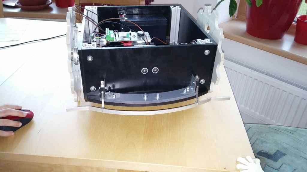
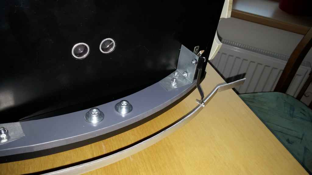
Afternoon I will send some pictures. Now I'm sending some pictures of complete mower.

20140406_191401.jpg


20140406_191416.jpg


20140406_191424.jpg


Thanks for help

Alex
Attachment: https://forum.ardumower.de/data/media/kunena/attachments/1183/20140406_191401.jpg/
 
Zuletzt bearbeitet von einem Moderator:
Hello Alex,

1. Yes, that's ok - the values will only make sense where a sensor (center-c, right-r or left-l) is connected. Not everything is required in this project, and left/right sensors are an optional example.

2. The current values are indeed strange. What ampere values do you get when measuring with an Ampere-meter instrument?

motor (+) --> instrument (Ampere) --> existing circuit

If the instrument shows correct Ampere values, what values (Voltage) does the current sensor output (output pin) when measuring with a Voltmeter?

What current sensor do you use? Maybe the actual (measured) current is higher than your sensor can measure...

Regarding RPM values, how do you measure RPM speed (what type of sensor do you use)? Did you try to verify that your RPM sensor is working correctly, e.g. measure the output pin voltage and slightly rotate the motor manually/by hand (disconnect power connector of the motor) and see if it actually gives a high/low pulse for each turn...

Regards,
Alexander
 
Hi Alexander,
Thank you for your answer.
I did measurement with following results :

mower only switched on : ampermeter:150mA, current sensor for mow:value 5-6
mow ON, max speed 33: ampermeter:260mA, current sensor:9-17, rpm:1400-1900
mow ON, max speed 48: ampermeter:330mA, current sensor:9-25, rpm:1600-2200
mow ON, max speed 100: ampermeter:470mA, current sensor:23-30(sometime jump to 16), rpm:2700-3000
mow ON, max speed 172: ampermeter:520mA, current sensor:22-34, rpm:3600-4200
mow ON, max speed 255: ampermeter:540mA, current sensor:5-9, rpm:4000-4230

current sensor : I'm using type up to 30A.

Alex
 
Motor used :
no load speed : 4000rpm
no load current : 300mA

hallsensor : A1302KUA-T

current sensor : Modul ACS712-30

Alex
 
Hello Alex,

both current sensor readings and rpm readings seem to fluctuate heavily, but the tendency (average over time) seem to be correct. I would try to more 'smooth' the values...

void readSensors()
...
motorMowSense = motorMowSense * 0.95 + ((double)abs(readSensor(SEN_MOTOR_MOW))) * 0.05;

Here, give the past more weight than the current measurement. Example: give past value weight 0.995 and current measurement 0.005. The sum of both weights must be always 1.0.

For the rpm values, maybe increase the measurement time:

void readSensors()
...
if ((millis() - lastMotorMowRpmTime) >= 500){

For example, increase from 500 ms to 5000 ms.

I hope this will give better results. Last but not least for the rpm measurement, exact values are not necessary - the speed control itself (motorMowControl) can be tuned by PID parameters so it acts time-delayed (pfodApp->Settings->Mow->Kp, Ki, Kd) and if those PID parameters are tuned correctly, rpm fluctation does not have any impact on the motor speed control.

PS: You can learn more about how to fine tune PID parameters for the Ardumower software-based motor speed controller in this article: http://tutorial.cytron.com.my/2012/06/22/pid-for-embedded-design/
Regards,
Alexander
 
Hi Alexander,

thank you for your answer, I will try software changes and give you information about situation.

But what I do not understand is last value :
mow ON, max speed 255: ampermeter:540mA, current sensor:5-9, rpm:4000-4230
Here is current from sensor very low - as with motor switched off.

Regarding PID parameters : I will check info in your link, but are there any universal parameters for PID ?

Thanks

Alex
 
Hi Alexander,
now I tested SW modification.
Change for RPM from 500 to 5000ms is very good and now RPM measurement is quite stable and also modulation is working ( but PID need some adjustments ), but current mesurement is still very strange.
I tried disconnect output signal from current measurement board and when I started mow motor, in pfod App current increased from 10 to 30 with disconnected output signal... there must be other problem. What must be measured to trace a problem ?

Thank you for help

Alex
 
Hello Alex,

if you disconnect an input signal, the signal is undefined and such an undefined input is a random signal. The easiest is to simply return 'nothing' for that specific sensor in your robot config (e.g. aml50.h):

int readSensor(char type){
...
// case SEN_MOTOR_MOW: return(analogRead(pinMotorMowSense)-motorMowSenseZero); break;

Comment out the line as shown above, and it will return the default (0) for such sensor.

Otherwise it will still call 'analogRead' and if that pin is 'open' (or not connected to GND), analogRead will give random values.

Regards,
Alexander
 
@Alex: regarding the PID parameters, the default work for many motors, maybe not for all.

PID quick introduction:

P: the P (proportional) part computes the difference between speed set-value and current value. If P is too small, the speed control runs slow and the set-value (here pink) is never completely reached (remaining error):

clip_image009_thumb.jpg


If P is high, the speed control is fast, but starts to oscillate.

clip_image013_thumb.jpg


Typically, you set P to a value so that it doesn't oscillate and additionally, you will use I (integral) and D (differential) parts.

I: The integral part only computes the sum of the differences between set-value and current value and so eliminates the remaining error. However, it cannot solve the oscillation.
clip_image019_thumb1.jpg


D: The differential part only computes the change of difference between set-value and current value. If the difference reduces (negative change), this adds an additional damping when reaching the set-value.

clip_image023_thumb1.jpg


When all parameters are tuned, there's no oscillation and no remaining error. It may require some trial-and error.

Regards,
Alexander
 
Hi Alexander,

thank you for xour answer. Why I'm still doing tests with current measurement for mow motor is, that measured values in pfod App are very strange. Likke, that on maximum speed (255) is measured current value lower than on lower speeds. Also I tried to give some ( I nearly stopped a motor ) braking torque to output shaft and there wasn't any current increase. So now I need a trace where is a problem.

Alex
 
Hello Alex,

You could add a voltmeter to the sensor's output pin, and watch the voltage on your voltmeter's display - it should increase while increasing motor current. If it suddenly decreases at a certain current, your sensor has a damage (is broken)...


Code:
Voltmeter GND ------- sensor GND
Voltmeter IN  ------- sensor OUT


Regards,
Alexander
 
Hi Alexander,
I think now is situation more clear. I did a meaurements with following results :

current sensor 30A - only conneceted to VCC 5V - output voltage 0V

current sensor 5A - only connected to VCC 5V - output voltage 2.5V

When motor mow started, voltage from 30A still 0V and from 5A sensor is changing ( increasing ). For me it's clear - 30A sensor is broken. For me is stange why 30A sensor is broken, maybe bad manipulation.

Alex
 
Hello Alex,

it might be possible that your 30A sensor doesn't use a VCC/2 center point:

One would expect:
0V .. 2.5V => negative current
exactly 2.5V => zero current
2.5V .. 5.0V => positive current

However this sensor might use:
-5V .. 0V => negative current
exactly 0V => zero current
0V .. 5.0V => positive current

If center point is at 0V (so ADC value 0), you can set the zero point in the config (or via PfodApp->Settings->Mow) to zero:

int motorMowSenseZero = 0;

Regards,
Alexander
 
Hi Alexander,

Current sensor is finally destroyed. I measured also output voltage with load and is still 0. I checked also complete board under microscope and I found mechanical ( !! ??? ) damages on the body of the main IC.

It's question if it's necesary use 30A current sensor for mow motor. For normal 40W motor is enough 5A current sensor.

Alex
 
Hello Alex,

I discovered the same mechanical damages on some of my current sensors (5A type) under the microscope - although they are working fine...

Yes, for a 40W motor a 5A sensor will be sufficient (40W / 24V => 1.6A). The 30A type was designed for mower motors using more power. Now I think we should change to 5A type in our schematics too - I had a 120W motor in mind when designing it... (120W / 24V => 5A).

Regards,
Alexander
 
Hi Alexander,

ok. Only one additional question regarding charging : is there any idea where to place charging pins on DIY chassis ? And is current sensor 5A enough for charging ? My plan is use as power source for charging normal auto(motocycle)-charger.

Alex
 
Hi Sven,

thank you, but this link : ardumower.de/index.php/de/forum/software...a-few-questions#2381
isn't working.

Pictures from chassis thread I already checked, but I can't see charging pins on the mower body.

Parallel with charging I'm now working also on the perimeter ( sender, receiver ) - I found, that coil is 85mH and 5830 windings, but what is wire diameter and coil is without metal core ?

Sorry for a lot of question

thanks

Alex
 
Hi,

thank you. I had also this idea, but what will happen during raining ? Is there any risk that water will make a short circuit between pins and discharge ( damage ) battery ?

Alex

edit : but when I will place plastic board (4mm) under each metal plate, then no short circuit risk.
 
@Alex: Regarding the perimeter coil, I don't know the wire diameter too, however I think the smaller the better. There is no much current (uA) that will flow through. Also, I have tested a small 100 mH coil (12mm x 16mm x 5mm) yesterday, and it works fine too using a LM386 amplifier (200x amplification)...
 
Oben