Du verwendest einen veralteten Browser. Es ist möglich, dass diese oder andere Websites nicht korrekt angezeigt werden.
Du solltest ein Upgrade durchführen oder einen alternativen Browser verwenden.
Du solltest ein Upgrade durchführen oder einen alternativen Browser verwenden.
Configuration Problems Ublox
- Ersteller MowerMows
- Erstellt am
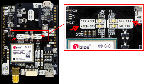
What can you see on the LEDs?

The base and rover LEDs should be as follows:
Base LEDs
Rover LEDs
RTK GPS test (invalid, float, fix) and FIX robustness and correctness
The base and rover LEDs can be used for trouble-shooting. Verify that the LEDs are acting as described below.
The base and rover LEDs should be as follows:
Base LEDs
| GPS>XBEE | should blink - your base module is sending satellite reference data to your rover module (via the XBee module) |
| XBEE>GPS | should be OFF - your base module should not receive any XBee/reference signal |
| GPS FIX | should blink - your base module has found a valid GPS signal |
| NO RTK | should be ON - your base module is not performing RTK (real time kinematic) |
| GPS>XBEE | should be OFF - your rover module should not send any XBee signal |
| XBEE>GPS | should blink - your rover module is receiving satellite reference data from your base module (via the XBee module) |
| GPS FIX | should blink - your rover module has found a valid GPS signal |
| NO RTK | should be OFF - your rover module has found a RTK FLOAT or FIX (is performing real-time kinematic) |
Thank you. I will check this.
I only checked the Rover LEDs: XBEE>GPS blinks, the other LEDs were off.
Question:
1. Is there any manuals to configure these moduls on my own?
2. How do base and rover know from each other? Is there any preconfiguration? Is there any source code of this preconfiguration?
I only checked the Rover LEDs: XBEE>GPS blinks, the other LEDs were off.
Question:
1. Is there any manuals to configure these moduls on my own?
2. How do base and rover know from each other? Is there any preconfiguration? Is there any source code of this preconfiguration?
Look here on first page, you find infomation and configuration files for the base, rover and the xpee cards from BenPan. I think you can use it. But check it with the settings from the wiki sunray which I have post here. (1) XBee Verbindung falsch rum | Ardumower
You can also find cofiguration files on github, see here Sunray/ublox_f9p_configs at master · Ardumower/Sunray (github.com)
You need the Ublox and Xbee tool for configuration. Normally the cards are configurated by Marotronics. I did also not configurated cards and made it myself.
If you would like I can help by Teamviwer remote session. But I am not a profi, I made it only one time for my base and rover.
The base and the rover die have one ID which you can change with the XBee tool. You must change it, if one of your neighbour did have also an Ardumower between 10km arear. Because then your Ardumower did not know which base your base.
Good luck.
Willi
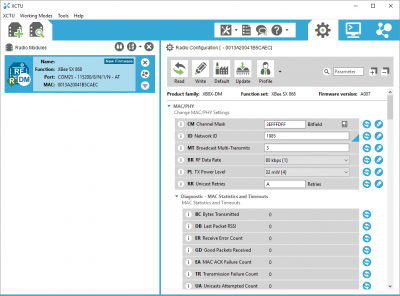
Here the XBee configuration:
Network ID: 1985
Broadcast Multi-Transmits: 3
RD Data Rate: 80 kps
TX Power Level: 32 mW
Unicast Retries: A
-
Routing/Messaging Mode: Standard Router[0]
Broadcast Hops: 0
Network Hops: 7
Mesh Unicast Retries: 1
-
Destination Address High: 0
Destination Address Low: FFFF
Transmit Options: 40
Node Identifier:
Network Discovery Back-off: 82
Network Discovery Options: 0
Cluster ID: 11
-
Encryption: Disabled [0]
AES Encryption Key:
-
Baud Rate: 115200
Parity: No Parity [0]
Stop Bits: One stop bit [0]
Packetization Timeout: 3
Flow Control Threshold: 11D
API Enable: Transparent Mode [0]
API Options: API Rx Indicator - 0x90 [0]
-
DIO0: Commissioning Button
DIO1: Disabled
DIO2: Disabled
DIO3: Disabled
DIO4: Disabled
DIO5: Assoc. Indicator
DIO6: Disabled
DIO7: CTS flow control
DIO8: Sleep Request
DIO9: ON/SLEEP Output
DI10: RSSI PWM0 Output
DI11: Disabled
DI12: Disabled
DOUT: UART_DOUT
DIN: UART_DIN
DI15: SPI_MISO
DI16: SPI_MOSI
DI17: SPI_SSEL
DI18: SPI_SCLK
DI19: SPI_ATTN
Pull Direction: FFFFF
Pull-Up: FFFFF
PWM0: 0
PWM1: 0
Associate LED Blink Time: 0
RSSI PWM Timer: 28
-
Sleep Mode: Normal
Sleep Options: 2
Number of Cycles Between Sleep: 1
Sleep Time: 190
Wake Time: 1F40
Wake Host Delay: 0
XBee module configuration
The XBee modules (LR/XLR) on ArduSimple PCB's are already configured. If you need to reconfigure for some reason, here's how to do so:- Connect ArduSimple PCB USB (XBee side) to your PC
- Download XCTU software: https://www.digi.com/xctu
- Start XCTU
- Windows: If your the COM port for the XBee is not found, start Windows device manager, right-click on XBee USB device, choose 'update driver->find on this computer->choose from list on my computer' and finally choose 'Digit International->Digi USB Serial Port'
- In XCTU, choose 'Add radio module' and choose the COM port

- Settings found on the XBee SX 868 (Firmware version A007):
Network ID: 1985
Broadcast Multi-Transmits: 3
RD Data Rate: 80 kps
TX Power Level: 32 mW
Unicast Retries: A
-
Routing/Messaging Mode: Standard Router[0]
Broadcast Hops: 0
Network Hops: 7
Mesh Unicast Retries: 1
-
Destination Address High: 0
Destination Address Low: FFFF
Transmit Options: 40
Node Identifier:
Network Discovery Back-off: 82
Network Discovery Options: 0
Cluster ID: 11
-
Encryption: Disabled [0]
AES Encryption Key:
-
Baud Rate: 115200
Parity: No Parity [0]
Stop Bits: One stop bit [0]
Packetization Timeout: 3
Flow Control Threshold: 11D
API Enable: Transparent Mode [0]
API Options: API Rx Indicator - 0x90 [0]
-
DIO0: Commissioning Button
DIO1: Disabled
DIO2: Disabled
DIO3: Disabled
DIO4: Disabled
DIO5: Assoc. Indicator
DIO6: Disabled
DIO7: CTS flow control
DIO8: Sleep Request
DIO9: ON/SLEEP Output
DI10: RSSI PWM0 Output
DI11: Disabled
DI12: Disabled
DOUT: UART_DOUT
DIN: UART_DIN
DI15: SPI_MISO
DI16: SPI_MOSI
DI17: SPI_SSEL
DI18: SPI_SCLK
DI19: SPI_ATTN
Pull Direction: FFFFF
Pull-Up: FFFFF
PWM0: 0
PWM1: 0
Associate LED Blink Time: 0
RSSI PWM Timer: 28
-
Sleep Mode: Normal
Sleep Options: 2
Number of Cycles Between Sleep: 1
Sleep Time: 190
Wake Time: 1F40
Wake Host Delay: 0
Here you can download the Ubloxx software: u-center | u-blox
You can decide between two ways, you can use the configuration files or you use the parameters of the Wiki.
Good luck!
If the parameters are right then you have to do point 12 of the Sunray Wiki. After them the rover did know how much away is it from the base. And then you can record the first perimeter on your yard.This means: in normal case: just plug in the rover gps receiver and base gps receiver and it should work. --> There is no configuration to do?
Good luck!
Now there is still another problem...
I always get the output: "ERROR: GPS receiver is not responding"
--> This means there is no communication to the gps board, am I right?
Questions:
- Is is important to have good GPS communication for that reason?
- If it is a common issue: how can I fix this?
I set the debug output of UBLOX on and get following result:
Sending: CLS:CFG ID:RATE Len: 0x0 Payload:
sendCommand: Waiting for ACK response
waitForACKResponse: TIMEOUT after 1100 msec.
ERROR: GPS receiver is not responding
trying baud 115200
Thank you.
Okay, I think got the failure but I really dont understand:
1. GPS Serial communication is on Pin RX1 & TX1 on ardusimple board
2. GPS Serial communication is on Header P5 on ardumower board
3. GPS Serial communication is on Pin 0 (TX) and Pin 1 (RX) on Grand Central Board M4
--> Pin 0 & Pin 1 = Serial1 on Grand Central Board M4 but in sunray code it is Serial 4 (config.h, line 430)?
Can someone explain this?
If I understand, then you did have the problem only on the Ublox Board Rover, is it so? On the Ublox Base board, you did reach the satelit signal in the Ublox center? Or can you see the satelit signal on both cards?
Did you connect the Ublox rover board as following? IOREF is connect on the Ublox to 3,3V?

Did you connect the Ublox rover board as following? IOREF is connect on the Ublox to 3,3V?

I have not make any change on the Sunray code for other serial configuration. Only my Ublox cards was not configurated, so that the LEDs on it was wrrong. As I had make the right configuration on both Ublox cards by the Ublox center tool, the cards was speaking together.


