Charger error

etmilosk

New member
Hello everyone,

This is Milos from Bosnia, I already wrote to you in this thread when I was just starting to build my Ardumower.

I am currently very close to finishing it and I have some more questions for you guys. I didn't have time to write in the meantime, but once I finish my Ardumower I will make a very detailed post about my build experience and I plan to be active on the forums.

I currently have a problem with CHARGER ERROR.

Let me please first explain how I set up my mower so you can better understand what is going on and hopefully help me.

My Ardumower is powered by two lead (Pb) batteries connected in series (24V).

My charger is a simple DC power supply which doesn't do any kind of current sensing or battery management.

I want the Arduino to monitor the charging current and control the charging.

I set up the charging as described in wiki page, see this screenshot for details:

PCB%20charging%20screenshot.jpg


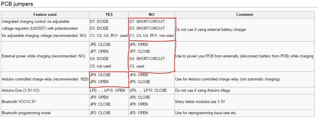
I have done everything that is circled in red:

D7 - installed and then short-circuit with a piece of wire
D3 - installed and then short-circuit with a piece of wire
C1, C4 - installed and then short-circuit with a piece of wire
U4, RV1 - not used, never installed

JP6 - Open
JP7 - Closed
D4 - Short-circuit
C5 - Used

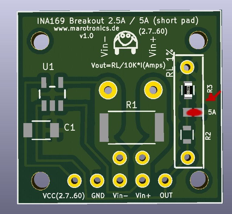
For the U5 I have ACS712 module connected instead of the INA169 module.

My batteries are connected to the board through the Battery connector (P43) and my charger contacts are connected through the Charger connector (P42).

The mower runs fine in manual mode but when I put it in Auto mode (via phone app), the wheels rotate a bit to the back (reverse) and state changes from OFF to STATION CHECK, and it waits for several seconds and then goes into error state (state is ERROR and robot beeps continuously). When I check the errors in the app, there is CHARGER error.

Even if I try to connect the charger to the charger connector, the same thing happens.

If I go to Settings -> Battery while the charger is not connected, it says (for example):

Charging voltage: 24.6 Charging current: 0.00 A

When I connect the charger, it shows the same thing, only this time the voltage is higher (it displays voltage a bit lower than the charger output voltage).

The relay never switches on/off.

Can you please tell me what is going on, why is it not detecting the charger properly?

Maybe my combination of diodes, capacitors and jumpers is not correct?


Thank you, any help is highly appreciated.


Milos
 
I forgot to mention that I use software version 1.0.2a3-Azurit with pcb V1.2 and Arduino Mega.

Thanks everyone, I'm looking forward to your reply!
 
Hi Milos,

I tried to mail you, but I think the private-mail of the forum is a bit broken?

Some background of myself:
- today I have my second ardumower up and running! Collision of two ardumowers leads to complex behaviour..
- it's my third board.. The first I screwed up, but hey, I'am not a technician!

If J4 is closed and J5 is open, the relay will only work if the voltage of the battery is below the configured thresshold. Is that the case?
What you could try is to open J4 and close J5. In that case the relay should always work => testing the circuit

On my first "learning board" I also had some issues with charging.
In my case the relay switched on/off continuously and I could not find the cause. After replacing the INA169 it worked like a charm..

Is there any specific (valid) reason not to use the INA 169?

As I wrote above, I am not a technician, and the ardumower is one of my first projects (after builing a CNC-machine).
As I do not know your experience with (building / composing) electronics, a few really basic questions:
- did you check your solderings => once was searching for two days, to find out that I had created an insufficient contact..
- did you align the diodes properly, especially D10 underneath the relays (as you wrote D7 and D3 are bridged)

Kind regards,

Woody
 
Hello Milos
I still have some waiting in the hope that somebody will help the better read and write English when I can.
I can unfortunately only poor English and that's a while since I was at school. That's why I read the text and answer it via Google Translate. I hope that what I write characterized as not loses its meaning.

In principle, it is so that the software is designed for the INA169. I can only recommend it.
The Ina169 sets the power to complete in a voltage range of 0-5V
the Ina169 from the shop has a range of 2.5A and 5A. Is set
That is easier said at e.g. the 5A current setting:
0A = 0V
5A = 5V
We have previously also the ACS sensor used but this has caused many problems.
The advantage of the INA169 are even the greater resolution and a quieter reading of only hardly varies.
A disadvantage is that the current can flow in only one direction so that the sensor does work properly. but playing on the 1.2 Board not matter.
The ACS 5A Works has a very different

0A correspond approximately 2.5V
5A whichever one or output correspond either 0V or 5V.

Therefore, another mathematical formula is needed to detect the flow even if the two versions.

In the Moverc.ppp file you can select the sensor used because the old code it is still present.

There are 2 ways that you have to test around depending on how you connect the input of the ACS as input or output.
Whether the code is still correct, I can not say.

When you enter there at chgSelection = 0 then you see what is spent on values ​​in the serial console. - But that is then not the power but they Sensor values ​​from 0- 1023rd

Please try to stick to the recommended components because we can then better help. Of course, he always went several ways. For us, it falls then very difficult to help someone because we can not understand its building steps and evl error in the wiring. Therefore, we are all working with the components from the shop to have a uniform standard.
The jumper settings I have not checked now because I would then again in plan check.

Mover.cpp
variant 1 - 0 then you see what is spent on values ​​in the Serielen console

Code:
// Sensorausgabe Konsole      (chgSelection =0)
  // Einstellungen ACS712 5A    (chgSelection =1   /   chgSenseZero ~ 511    /    chgFactor = 39    /    chgSense =185.0    /    chgChange = 0 oder 1    (je nach  Stromrichtung)   /   chgNull  = 2)
  // Einstellungen INA169 board (chgSelection =2)
  chgSelection    = 0;
  chgSenseZero    = 511;        // charge current sense zero point
  chgFactor       = 39;         // charge current conversion factor   - Empfindlichkeit nimmt mit ca. 39/V Vcc ab
  chgSense        = 185.0;      // mV/A empfindlichkeit des Ladestromsensors in mV/A (Für ACS712 5A = 185)
  chgChange       = 0;          // Messwertumkehr von - nach +         1 oder 0
  chgNull         = 2;          // Nullduchgang abziehen (1 oder 2)


variant 2 ACS 5A

Code:
// Sensorausgabe Konsole      (chgSelection =0)
  // Einstellungen ACS712 5A    (chgSelection =1   /   chgSenseZero ~ 511    /    chgFactor = 39    /    chgSense =185.0    /    chgChange = 0 oder 1    (je nach  Stromrichtung)   /   chgNull  = 2)
  // Einstellungen INA169 board (chgSelection =2)
  chgSelection    = 1;
  chgSenseZero    = 511;        // charge current sense zero point
  chgFactor       = 39;         // charge current conversion factor   - Empfindlichkeit nimmt mit ca. 39/V Vcc ab
  chgSense        = 185.0;      // mV/A empfindlichkeit des Ladestromsensors in mV/A (Für ACS712 5A = 185)
  chgChange       = 0;          // Messwertumkehr von - nach +         1 oder 0
  chgNull         = 2;          // Nullduchgang abziehen (1 oder 2)


variant 3 ACS 5A

Code:
// Sensorausgabe Konsole      (chgSelection =0)
  // Einstellungen ACS712 5A    (chgSelection =1   /   chgSenseZero ~ 511    /    chgFactor = 39    /    chgSense =185.0    /    chgChange = 0 oder 1    (je nach  Stromrichtung)   /   chgNull  = 2)
  // Einstellungen INA169 board (chgSelection =2)
  chgSelection    = 1;
  chgSenseZero    = 511;        // charge current sense zero point
  chgFactor       = 39;         // charge current conversion factor   - Empfindlichkeit nimmt mit ca. 39/V Vcc ab
  chgSense        = 185.0;      // mV/A empfindlichkeit des Ladestromsensors in mV/A (Für ACS712 5A = 185)
  chgChange       = 1;          // Messwertumkehr von - nach +         1 oder 0
  chgNull         = 2;          // Nullduchgang abziehen (1 oder 2)


Gruß
Uwe

-----------------------------------------------------------------------------


Hallo Milos
Ich habe noch etwas gewartet in der Hoffnung das dir jemand hilft der besser Englisch lesen und schreiben kann als ich.
Ich kann leider nur schlecht Englisch und das ist schon eine weile her seit ich in der Schule war.
Deswegen lese ich die Text und antworte darauf über Google Translate.
Ich hoffe das das was ich da schreibe dadurch nicht seinen Sinn verliert.

Prinzipiell ist es so das die Software für den INA169 ausgelegt ist. Ich kann ihn auch nur empfehlen.
Der Ina169 setzt die Strom komplett um in ein Spannungsbereich von 0-5V
der Ina169 aus dem Shop hat ein Messbereich von 2,5A und 5A. Ist einstellbar
Das heißt vereinfacht erklärt bei z.B der 5A Strom Einstellung:
0A =0V
5A= 5V
Wir haben vorher auch den ACS Sensor verwendet aber dieser hat viele Probleme verursacht.
Der Vorteil von den INA169 sind einmal die größere Auflösung und ein ruhigeren Messwert der nur kaum schwankt.
Ein Nachteil ist das der Strom nur in einer Richtung fließen kann damit der Sensor richtig arbeiten tut.
Spielt aber auf den 1.2 Board keine rolle.
Der ACS 5A arbeitet dagegen ganz anders

0A entsprechen ca 2,5V
5A je nachdem was ein oder Ausgang ist entsprechen entweder 0V oder 5V.

Daher wird auch bei beiden Versionen eine andere Mathematische Formel benötigt um den Strom zu erfassen.

In der Moverc.ppp Datei kann man den verwendeten Sensor auswählen weil der alte Code dafür noch vorhanden ist.

Dabei gibt es 2 Möglichkeiten die du testen musst je nachdem wie herum du den Eingang des ACS als Eingang oder Ausgang angeschlossen hast.
Ob der Programmcode noch stimmt kann ich leider nicht sagen.

Wenn du dort bei chgSelection =0 eingibt siehst du dann in der Seriellen Konsole was für Werte ausgegeben werden. - Das ist aber dann nicht der Strom sondern nur sie Sensorwerte von 0- 1023.

Versuche bitte bei den empfohlenen Bauteilen zu bleiben weil wir dann besser helfen können.
Selbstverständlich ging er immer mehrere Möglichkeiten.
Uns fällt es dann nur sehr schwer jemanden zu helfen weil wir seine Bauschritte und evl Fehler in der Verdrahtung nicht nachvollziehen können.
Daher arbeiten wir alle mit den Komponenten aus dem Shop um ein einheitlichen Standard zu haben.
Die Jumper Einstellungen habe ich jetzt noch nicht kontrolliert da müsste ich dann noch mal im Plan nachsehen.
 
Dear Woody and Uwe, thanks for your replies!

Woody:

I am a very technical person, and I have knowledge of electronics, mechanics and programming (Arduino, C, and VB), but I'm not really an expert. I'm learning about electronics and programming every day. I find electronics very very interesting. :)

I used the ACS current sensor instead of INA just in order to reduce the total price as much as I can. The whole project costs a lot for me so I tried to cut the costs as much as possible.

As for your suggestions, I believe my solders are good, I take a lot of care when soldering, but I didn't go through every solder pad again in order to check. All the diodes are oriented correctly.

Uwe:

Thanks for your reply. Although you translate from German to English with Google Translate, I can understand what you are saying and your help is very much appreciated. I see now how much easier is it to use recommended parts.

**************************************************

Here is what I did based on your suggestions:


I have only one INA169 module (I ordered it for the perimeter sender) and today I moved the INA from perimeter sender to the main PCB. Uwe, I checked in the mower.cpp file and my chgSelection is 2 (chgSelection = 2).

The mower is now behaving much better, but still not totally as it should.

This is the current behaviour:

- No charger connected:

App > Settings > Battery: Charging Voltage: 0.0V, Charging Current: 0.0A

Station LED on pcb is turned off.

State is OFF.

- Charger connected:

App > Settings > Battery: Charging Voltage: 27V, Charging Current: 0.0A

Station LED on pcb is turned on!

State is CHARG.

- App > Commands > Auto:

Mower motor turns on, state is FORW and wheels turn forward - no more Charger error

**************************************************

So, now when I connect the charger, it is obvious that the board detects the charger, but it is not charging the batteries for some reason. The battery voltage only decreases, even when the charger is connected.

The relay never switches (it never works), not even when I set the charging threshold below the current battery voltage or when I swap the JP4 and JP5 jumpers.

I did a small experiment: I thought that maybe the circuit that powers the relay coil is broken, so I took off the plastic relay cover and tried switching on the relay by hand, but again, nothing happens. If I connect the charger and switch the relay by hand, the Charging Current is still 0.0A.

I have a smart DC-DC buck converter connected in series with my charger (Charger -> DC-DC converter -> Ardumower) which I use to step down the voltage and to limit the current (the max current is set to 2A). The converter has an option to display the current that is being drawn from it, and it displays that Ardumower draws only 0.017A when connected.


Thanks for all your help!

Milos
 
Hello Milos
I have another question
Do you have the charge control stocked Yes or no?
Can you ever please take a photo of the 1.2 board making as close as possible and sharp that I may know the Bautele and reinstellen here.
How did you do the ACS current sensor wired?
Can you read and make simple measurements for voltage and resistance is a circuit diagram?

Hallo Milos
Ich habe noch eine Frage
Hast du die Laderegelung bestückt Ja oder nein ?
Kannst du mal bitte ein Foto von der 1.2 Platine machen möglichst nah und scharf damit ich die Bautele erkenne und hier reinstellen.
Wie hast du den ACS Stromsensor verdrahtet ?
Kannst du ein Schaltplan lesen und einfache Messungen für Spannung und Widerstand machen ?

Gruß
Uwe
 
Hello Uwe, thanks for your help!

I solved the charger problem!

I didn't mention to you that I didn't have the U3 fitted. Place for U3 was empty on my board. I examined the schematic and I noticed that without U3 the current from the charger doesn't reach the relay.

I moved the INA169 from U5 to U3, and because U5 was now empty, I short-circuited it with a jumper.

I also found another problem, the place for R19 was empty and because of that, the coil of the relay didn't get the power. In the Platine Bauteile document, it says that R19 is a jumper, so I just short-circuited it with a piece of wire.

Now the relay has power and it switches on a couple of seconds after I connect the charger.

This is the current behaviour:

- No charger connected:

App > Settings > Battery: Charging Voltage: 0.0V, Charging Current: 0.0A

Station LED on pcb is turned off.

Relay is OFF.

State is OFF.

- Charger connected:

App > Settings > Battery: Charging Voltage: 29V, Charging Current: 0.8A (for example) and decreasing

Station LED on pcb is turned on!

Relay is ON.

State is CHARG.

There is one new problem now, the charging current that is detected by the INA169 is too low.
When I connect the charger, the real current is 1.9A but in App > Settings > Battery: Charging current is around 1A and it quickly decreases. After just 10 seconds it shows that current is below 0.3A and Arduino stops the charging. It can continue charging only if I set the "Battery is charged if current is below" to 0.0A.

I tried changing the parameters in App > Settings > Battery but it doesn't change the charging current.

I have some questions for you:

1. How do I adjust the charging current (to show correct value)?

2. What is Charging Bilanz, in English? I know what is charging current but don't understand what is Charging Bilanz (in the schematic, pin Charging Bilanz is connected to U5.

3. Is it safe to input 29 V to the Charger Connector?

4. Should I put a resistor in the place of R19? If yes, what value?

5. I have ordered more INA169 modules. Is it safe to use a jumper instead of U5 until my INA modules arrive?

6. In App > Settings > Battery, what is exactly Charge factor, Charge Sense Zero and Calibrate batChgFactor?


Thank you for all your help!


Milos
 
-->6. These parameters are only used if you select to use the ACS-sensor, instead of INA169. Check it in the code mower.cpp, approx. line 220, look for "chgSelection" .. it should be "2" (verify it with the comment there).

Greets,
Jem
 
Hallo
C1,C4,RV1,U4 darf nicht bestückt sein
D7,D3,D4 Drahtbrücke

R19 ist ein Vorwiderstand für das Laderelais. Da du wahrscheinlich 24V Betriebsspannung und ein 24V Relais verwendest kann dieser Widerstand gebrückt werden.
Will man auf Nummer sicher gehen kann man dort noch eine Diode einbauen. Diese würde dann verhindern das bei versehentlicher Verpolung der Ladespannung das Laderelais anzieht. Sollte z.B mit einer 1n4148 funktionieren. Was für ein Strom über das Relais läuft weiß ich gerade nicht aus dem Kopf. Evl einfach eine Diode nehmen die etwas mehr Strom aushält.

siehe auch hier http://www.ardumower.de/index.php/d...605-ardumower-board-version-1-2?start=20#8796 http://www.ardumower.de/index.php/de/forum/ardumower-platinen/605-ardumower-board-version-1-2?start=20#8824

Nun zu deinen Fragen
1.
Wenn ich es richtig im Kopf kann man den Strom noch in der Handy App kalibrieren für den ACS Stromsensor. Geht auch in der Ardumoer Code ist aber dort etwas schwieriger, weil man immer wider testen muss.
Das ist aber eigentlich nicht nötig.Ich gehe mal davon aus das du die INA aus dem Shop hast und nicht von Adafruit.
Die Originalen von Adafruit haben ein Messbereich von 5A.
Unsere aus dem Shop haben in der Auslieferung ein Messbereich von 2,5A. Für den 5A Messbereich muss eine kleine Brücke geschlossen werden. Hier siehst du wo

INA169.jpg


jetzt sollten eigentlich die richtigen Werte angezeigt werden. Kalibrierung sollte eigentlich nicht nötig sein.

2.
Die Bilanz U5 wird nicht gebraucht und kann mit einer Drahtbrücke geschlossen werden. Es war mal angedacht den Gesamten Strom des Mowers zu erfassen. Die Idee wurde aber nicht weiter verfolgt und wird auch nicht unterstützt.

3.Unser Standard Akku hat 25,9V und die Ladeschlussspannung des Ladegerätes hat ca 29,4V. Dürfte also kein Problem sein.

4.
Nein bei einem 24V Relais und 24V Spannung kann da eine Brücke oder zum Schutz eine Diode rein. Ein Widerstand wäre nur erforderlich wenn du 24V Spannung und eine 12V Relais hast.
Siehe dir auch nochmal die beiden Links oben und die Bilder dazu an.

5.ja U5 ist ohne Funktion und muss daher gebrückt werden.

6. Müsste ich jetzt selber testen und bin nicht 100% Sicher. Wenn ich es aber richtig im Kopf habe ist das nur relevant beim ACS Stromsensor. Ladefaktor, Lade Sense Null und Kalibrieren batChgFactor haben soviel ich es noch weiß nur auf den ACS Einfluss.
Wenn es da Probleme gibt müsste ich selber nochmal testen. Dann melde dich nochmal


für den Betrieb empfehle ich
j6 offen j7 geschlossen
j4 geschlossen j5 offen

Gruß

Uwe

----------------------------


Hello
C1, C4, RV1, U4 may not be equipped
D7, D3, D4 jumper

R19 is a resistor for the charging relay. Since you probably 24V operating voltage and a 24V relay using this resistance can be bridged.
Will you can play it safe you there yet installing a diode. This would prevent the case of accidental reverse polarity of the charging voltage attracts the charging relay. If e.g. operate with a 1N4148. What passes for a current through the relay I do not know just from the head. Evl simply take a diode withstand a little more power.

see also here
www.ardumower.de/index.php/de/forum/ardu...on-1-2?start=20#8796
www.ardumower.de/index.php/de/forum/ardu...on-1-2?start=20#8824

Now to your questions
1.
If I right in the head may be the current still calibrate the mobile app for the ACS current sensor. Goes well in the Ardumoer code but there is a little more difficult because you must always test resist.
But that is not really nötig.Ich'm assuming that you have the INA from the shop and not from Adafruit.
The originals of Adafruit have a measuring range of 5A.
Our from the shop have in delivering a range of 2.5A. For the 5A range a little bridge must be closed. Here are where

INA169.jpg


now the correct values ​​should actually be displayed. Calibration should not really be necessary.

2.
Record U5 is not needed and can be closed with a jumper. It was even planned to complete to capture power of Mower. The idea was not pursued further and is also not supported.

3.Our has Standard battery 25,9V and the charging voltage of the charger is approx 29,4V. Might not be a problem.

4.
No with a 24V relay and 24V voltage can in there a bridge or to protect a diode. A resistor will be necessary only if you have 24V and a 12V relay.
See you again and the two links above and the associated images to.

5.
ja U5 has no function and must therefore be bridged.

6. Should I now test myself and am not 100% sure. If I but have in my head right is the only relevant when ACS current sensor. have load factor, loading Sense zero and calibration batChgFactor much I still know only the ACS influence.
If there are problems, I have to myself again test. Then login again


for the operation, I recommend
j6 open j7 closed
j4 closed j5 open

greeting

Uwe
Attachment: https://forum.ardumower.de/data/media/kunena/attachments/1259/INA169.jpg/
 
Zuletzt bearbeitet von einem Moderator:
Uwe and Jem, thanks for your help!

Jemihi schrieb:
-->6. These parameters are only used if you select to use the ACS-sensor, instead of INA169. Check it in the code mower.cpp, approx. line 220, look for "chgSelection" .. it should be "2" (verify it with the comment there).

Yes, I have checked that and it is set to 2 (I'm using INA169 now).

Uwe, I tried soldering the solder pad on the INA169 but then the charging current is not detected at all (it is 0.0V all the time). I removed the solder from the solder pad again and it again shows current but it very quickly drops to 0A.

Can I use the timeout in the code to limit the charging time?

My DC-DC converter will only supply the current that the batteries need (for example, now the charger is connected to the batteries directly for about two hours and the current is only 0.170 A.

The jumpers are set as you recommended.

Now I have another problem with the perimeter sender, I will now open a new forum topic for that, if you could take a look there.


Thanks for all your help!

Regards,

Milos
 
Zuletzt bearbeitet von einem Moderator:
Hello everyone, it's me again!

I have updated the main mower code to newest version 1.0a5-Azurit, and the mower is behaving differently now regarding the charging.


This is current behaviour:

- No charger connected:

App > Settings > Battery: Charging Voltage: 0.0V, Charging Current: 0.0A

Station LED on pcb is turned off.

Relay is OFF.

State is OFF.

- Charger connected:

App > Settings > Battery: Charging Voltage: 29V, Charging Current: 3.7A (real current is 1.9A)

Station LED on pcb is turned on!

Relay is ON.

State is CHARG.

When I disconnect the charger, in the App, the Charging Current immediately drops to 0.0A, but the Charging Voltage stays high (around 26V) and it drops very very slowly. The relay also stays on (relay contacts stay connected).

I have to go to Commands > OFF to put the mower in OFF state for the relay to disconnect.

I have tried with both combinations of jumpers:

J4 Closed J5 Open
J6 Open J7 Closed

and

J4 Open J5 Closed
J6 Closed J7 Open

but it's behaving the same.


Do you have any idea why is it behaving that way?


Also, can you confirm the use for this line of code in the Mower.cpp

Code:
chargingTimeout = 12600000; // safety timer for charging (ms) 12600000 = 3.5hrs


Is the Arduino going to interrupt charging after 3.5hrs regardless of the charging current?
If yes, what is the mower going to do, exit the station and return to AUTO mode?


Thanks

Milos
 
Hallo Milos,
wenn du die Kondensatoren C1 und C4 oder die Widerstände R27 oder RV1 bestückt hast dann entferne sie bitte von den Board.
Diese verursachen zum Teil die Probleme. Die Kondensatoren laden sich auf und speichern die Spannung. Wenn der Mower die Ladestation verlässt wird immer noch die Ladespannung angezeigt obwohl an den Ladekontakten keine Spannung mehr anliegt.

Ladespannung im der App und in der Seriellen Konsole wird immer angezeigt solange der Mower in der Ladestation steht. Über das anlegen der Ladespannung an den Ladekontakten weiß der Mower das er die Ladestation gefunden hat und die Antriebsmotoren abschaltet.
Ein laden findet nur dann statt wen auch ein Ladestrom fließt.
Ein laden muss ja nicht unbedingt stattfinden wenn er in der Ladestation steht. Es soll ja auch ausserhalb der Mähzeiten oder z.B bei Regen zurück in die Ladestation fahren ohne zu laden. Über die Ladespannung weiß er dann das er die Ladestation gefunden hat und bleibt stehen.

Die Werte für die Batterie musst du evl anpassen an dein Akku: Die werte die dort stehen sind die Werte fü den empfohlenen Akku und nicht für andere Akkus wie z.B Blei.


Die Station LED ist auch wichtig.
Sobald er in der Station steht fängt die LED an zu Leuchten. Die Spannung dafür erhält er nicht über den Mower sondern über die Ladekontakte bzw den Schleifensender.
Im Schleifensender sitzt ein INA drin wo durch die LED ein kleiner Strom fließt oder wenn geladen wird ein großer Strom fließt.

Solange durch diesen INA in der Station ein Strom fließt weiß die Station das der Mower in der Station steht. Während der Zeit wird dann der Schleifensender abgeschaltet. Sobald dort kein Strom mehr fließt wird der Schleifensender wider eingeschaltet.

chargingTimeout = 12600000; // Sicherheitstimer für die Aufladung (ms) 12600000 = 3,5h
Ja das ist eine eingebaute Sicherheitszeit nachdem das Laden unterbrochen wird.

Wenn kein Timer gesetzt ist schaltet sich der Mower dann ab.

Da bist vor kurzen noch ein Fehler in der Uhr war konnten wir das automatische Mähen noch nicht testen.
im Normalfall muss man Die Uhr aktivieren und die Mähzeiten eintragen. Dann müsste er während der Zeiten mähen und ausserhalb der Zeiten in der Ladestation warten ohne sich abzuschalten.

Gruß
Uwe

__________________________________________________________________________________________

Hello Milos,
if you have the capacitors C1 and C4 or the resistors R27 or RV1 fitted then please remove from the board.
These sometimes cause problems. The capacitors charge and store the voltage. If the Mower the charging station, the charging voltage is leaving still displayed although bears no voltage at the charging contacts.

Charging voltage in the app and in the serial console is always displayed as long as the mower is in the charging station. About the charging voltage at the charging contacts or edit the white Mower he has the charging station and found the drive motors off.
A load takes place only who a charging current is flowing.
A load must not indeed necessarily take place when it is in the charging station. It is indeed also outside the mowing time or e.g. in rainy drive back into the charging station without having to reload. then over the charging voltage does he know that he has the charging station found and stops.

The values ​​for the battery you have to adapt evl on your battery: The values ​​that are available there, the values ​​fo the recommended battery and not with other batteries such as e.g. lead.


The station LED is also important.
Once he is on the station begins the LED lights on. The voltage for he does not get on the Mower but via the charging contacts or the loop transmitter.
In loop transmitter INA sitting inside where the LED a small current flows or a large current is flowing when loaded.

As long as these by INA in the station, a current flows know the station that the Mower in station stands. During the time then the loop transmitter is switched off. Once there flows no current loop transmitter is switched resist.

chargingTimeout = 12600000; // Safety timer for charging (ms) 12600000 = 3.5h
Yes this is a built-in safety time after the charging is interrupted.

If no timer is set then the Mower switches off.

There you before short still an error in the clock was we could not test the automatic mowing.
Normally, you need to set the clock and submit it mowing time. Then he would have to mow during the times and outside the hours in the charging station without having to wait to switch off.

greeting
Uwe
 
Ich muss das jetzt mal loswerden: Uwe liefert hier im Forum eine großartige Unterstützung für Nachbauer ab, ich hoffe alle Interessierten wissen das zu schätzen. Seien die Fragen der Nachbauer auch noch so umfangreich, er hat eine Antwort. Deine Antworten sind einfach Klasse.

I have to say a small thank you: Uwe does a great support here in the forum for all the makers, I hope all makers appreciate this. The questions can be so extensive, but he has an answer. Your answers are simply great.
 
UweZ schrieb:
Da bist vor kurzen noch ein Fehler in der Uhr war konnten wir das automatische Mähen noch nicht testen.
im Normalfall muss man Die Uhr aktivieren und die Mähzeiten eintragen. Dann müsste er während der Zeiten mähen und ausserhalb der Zeiten in der Ladestation warten ohne sich abzuschalten.

__________________________________________________________________________________________


There you before short still an error in the clock was we could not test the automatic mowing.
Normally, you need to set the clock and submit it mowing time. Then he would have to mow during the times and outside the hours in the charging station without having to wait to switch off.


I just did some changes on the software last week and could test the timers, but only without a base.
After uncommenting checkTimer() i did some successful tests with timed mowing :)
Dont forget to fix the 6 - Days rtc issue => if ( (r.time.minute > 59) || (r.time.hour > 23) || (r.date.dayOfWeek > 7)


Kleine Info von mir zu den Timern.
Ich habe mich in den letzten zwei Wochen etwas mit der 1.04a Azurit beschäftigt, etwas erweitert und auch das zeitgesteuerte mähen mal ausprobiert, leider noch ohne Ladestation.
checkTimer() ist auskommentiert, einkommentieren und schon mäht er zeitgesteuert.
Zuvor den Bug if ( (r.time.minute > 59) || (r.time.hour > 23) || (r.date.dayOfWeek > 7) beheben.
 
Zuletzt bearbeitet von einem Moderator:
Thanks Uwe, I will check the capacitors and resistors tomorrow.

Alexander, I totally agree with you. Uwe's answers are so detailed that they represent a true treasure for this forum and for everyone's understanding of the Ardumower.

Alexander, could you please retype in English what Uwe said?

Google Translate sometimes does a good job but sometimes it's almost unusable.

I can understand what Uwe said about the capacitors, resistors and switching off the perimeter wire, but not the rest of what he said.

Thank you!


Regards

Milos
 
Due to a recent bug, we were not able to test the RTC timer mowing (it's fixed in latest release). It works by activating timers, setting mowing times and then the mower will mow during these time frames, but outside the time frames stay in the station.
 
Thanks Alexander!

I have partially solved the charging problem.

First, I have soldered the solder bridge (jumper) on the INA139, again, and now it shows the correct charging current.

I have checked my board:

C1 and C4 - not installed
RV1 - not installed
R27 - I think there is no R27, biggest resistor number I found is R26..?


Anyway, I think I have found the source of problem.

After I disconnect the charger, the pinChargingEnable stays high. I assume that this pin stays floating because there is no pull-down resistor for it. I have tried to connect it to GND after I disconnect the charger, and it immediately turns off the relay and the state changes from CHARG to OFF. I have tried to connect it through a pull-down resistor but I couldn't find a resistor of suitable value. I have tried many resistor values from 10 kOhm all the way down to 120 Ohm, but the resistance is still too high. I didn't have a resistor smaller than 120 Ohm to try it.

I think that a pull-down resistor on this pin might be a good idea for future design improvements.

However, since my INA169 now measures the current correctly, maybe I don't even have to do this. I will test it more in the next days and see.


Thanks everyone!
 
wenn der Jumper J5 geschlossen und der Jumper J4 offen ist zieht das Relais immer an sobald Spannung an den Ladekontakten vorhanden ist.
Wenn der Jumper J5 offen und der Jumper J4 geschlossen ist wird das Relais bei bedarf über den Arduino geschaltet.


if the jumper closed J5 and J4 jumper is always open to the relay switches on when voltage at the charging contacts is available.
If the jumper J5 open and the jumper J4 closed the relay is in need connected via the Arduino.
https://github.com/Ardumower/ardumo...5/Ardumower Haupt Platine V1.2 Schaltplan.pdf
Gruß
Uwe
 
Hello Uwe,

thanks for your reply.

Yes, I understand what is the purpose of the J4 and J5.

I have tried both combinations and the mower is always behaving the same, the relay stays connected after I disconnect the charger. As I said, perhaps this is not the problem for normal usage of the mower, now that my current sensor is correctly detecting the charging current.

Regards,

Milos

======================================================================================

Hallo Uwe ,

Danke für deine Antwort.

Ja, ich verstehe , was der Zweck der J4 und J5 ist .

Ich habe beide Kombinationen ausprobiert und der Mäher immer gleich verhält , bleibt das Relais angeschlossen , nachdem ich das Ladegerät trennen . Wie gesagt, vielleicht ist dies nicht das Problem für den normalen Gebrauch des Mähers ,jetzt , dass meine Stromsensor korrekt erkennt den Ladestrom .

Grüß,

Milos
 
Oben