Building instruction for the 1.3 board

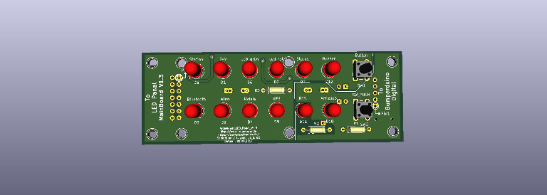
I just bought the 1.3 PCB board and waiting for it to arrive. I have reviewed some 1.2 building instructions however if someone can point me to the best (in English) building instructions for the 1.3 pub with pictures I would be really grateful

Also what is the benefit of using the Arduino Due over the Megga and is it fully implemented the code

regards
 
We are currently making the instruction manual for PCB1.3 (German) - After that I'll translate it into English. Meanwhile, there are:
-some photos and instructions (German) here: http://www.ardumower.de/index.php/d...d/1306-neues-board-neuer-bereich-wir-bauen-um -assemble drawings here: https://github.com/Ardumower/ardumo...tinen/megashield_svn_1.3_geschlossen/assemble -PCB drawings here: https://github.com/Ardumower/ardumo...megashield_svn_1.3_geschlossen/Platinenbilder -schematics here: https://github.com/Ardumower/ardumower/tree/master/pcb/Produzierte_Platinen/megashield_svn_1.3_geschlossen/schematics
 
Thanks for publishing the links. I will start on my board in a few days. Before I start work I want to get the Ardu mower mini working so that I know what to expect with the main build
On the version I want build I will use a petrol engine and control the motion with the Ardumower. I would prefer to build the system up in chunks. i.e. I do not want to put the whole board and every module on at first as this will make trouble shooting harder
other than the motor drivers (and motors) what else needs to be added to this board to make it functional. buzzer push button. Anything else for a minimal build.

Also I assume that for the final build I do not need ANY of the mower electronics as I will be controlling the petrol motor separately Y/N?

thanks again for your help

any idea on the timing of the German instructions as I can use google translate to get a rough translation
 
Hi Guys, I've already ordered PCB1.3, soldered and the whole thing seems to work nice so far (starting testing on field the coming days). But I noticed a really weird thing I do not understand: Why to measure battery voltage after diode D9? I find it wrong.
My issue was with that whenever the charge voltage pop up, on pinBatteryVoltage we measured the charge voltage (the charge either did not started or went on/off based on voltage/current settings).
In the attached picture you find what I did at the end: just cut that through on the PCB and fixed with a wire so now works according to my expectations.
Is there any reason to have it like on plans or it's just an error?
Attachment: https://forum.ardumower.de/data/media/kunena/attachments/3874/2017707113358.jpg/
 
Zuletzt bearbeitet von einem Moderator:
Hi Guys, I've already ordered PCB1.3, soldered and the whole thing seems to work nice so far (starting testing on field the coming days). But I noticed a really weird thing I do not understand: Why to measure battery voltage after diode D9? I find it wrong.
My issue was with that whenever the charge voltage pop up, on pinBatteryVoltage we measured the charge voltage (the charge either did not started or went on/off based on voltage/current settings).
In the attached picture you find what I did at the end: just cut that through on the PCB and fixed with a wire so now works according to my expectations.
Is there any reason to have it like on plans or it's just an error?
Attachment: https://forum.ardumower.de/data/media/kunena/attachments/3874/2017707113358_2017-07-07.jpg/
 
Zuletzt bearbeitet von einem Moderator:
Hi Forrest,
D9 isn't an error. The PCB 1.3 is made to work with the original Ardumower Charger and ArduMower Battery. The charging voltage is in this case always in the same range as the Battery Voltage (a litle higher). In charging state is only the current a point of interest. When you remove D9 an short this point you have two problems.
1. The measuring of current go's never to 0,1A in charging state.
2. The PCB1.3 is always Battery powerd in sation state.
The battery voltage is only interesting in the working mode. The diode D9 protects the voltage divider and the rest of the circuit when the battery is connected in reverse polarity.

It's nice and okay when your solution works fine for you. But not for the real ArduMower equipment.

regards

Jürgen
 
Thanks, clear now. I indeed use an own leftover pack of battery+own charger from another project. I see my issue was coming then from the charger: at the beginning the charging voltage is too high (that I guess won't happen with official charger, or at least mine drops the initial voltage too slow) so it did not started charging, so I had to set startChargingIfBelow too high. But then once charging has finished it stopped charging and immediatley swiched on again (due to too high startChargingIfBelow).

Anyway I love the 1.3 PCB, I find it very convenient, great work! I have much less noise picked up (to achieve that I also completely reworked the body of my mower) and with the Due +less odo interrupts the mower is nicely responsive. So thanks for the enormous work!
 
I have review the build videos and pictures of the 1.3 pcb. I am still unclear regarding all the jumpers (10 included) . On the board schematic I have found jumpers JP 1 to 13 except jumper #JP2. Can you point this out. Also in the wiki in your check list you refer to JP 1,4,6,7,8,10,11,12,13 also to JC 2,3,4,5,6,7, Are there two sets of jumpers??? or are the JC jumpers really JP jumpers. Also which are not used

I have reviewed the pictures however if someone could take some good photos of the jumper locations (without jumpers fitted) and then with the jumpers fitted for a basic configuration. it would be appreciated.

Also do you have a parts listing that relates to the part on the circuit board. The parts listing I received in the kit from the shop does not relate the part to the board.

Lastly I received 6 terminal blocks in the kit whereas there are at least 9 required. Do you fix this or do I need to contact the shop?
 
JC jumpers are not equal to JP jumpers. The JC ones are the voltage selectors for I2C devices/connectors, check page 31 of the schema. They are located between the I2C connectors and the Due board on the side where all the connectors are (in Vorderanschicht.jpg the top middle section). You only need to place a jumper on them if you also connect a device to their belonging port.
JP2 is the bluetooth key selector, you need to use it for initial config of bluetooth module, in normal operation it is removed. You find it on page 8 of the schema. On the board it is visible in Vorderanschich.jpg on the bottom left corner just next to the bluetooth hole 'matrix'.
 
I have constructed the PCB 1.3 and ready for power on. When I was using the mini I had a push button connected to pin 51 to control the mode of the mega. Each mode had a different number of beeps. I can not see the equivalent place to connect this on the pcb.

At initial power on all jumpers need to be disconnected

Then I need to adjust the DCDC voltage regulator to 9 volts before connecting JP1

I am using a mega NOT a due so do I connect JP 13.

At first I will not use BT WIFI IMU GPS so none of their jumpers will be enabled

Do I need to connect any other jumpers

Regards
Max
 
Everything seems to work fine on the PCB
I would be grateful if someone can confirm that the main power should be on when I connect to the mega with the usb cable. If I want to change parameters and upload code is there anything I need to be careful off. Do I need to change any jumpers.

Also what are the pins used for in the 8 by 7 pin block which is located on the left side of the board to the right of the LED's

regards
Max
 
Der Anschluss (2x7) ist ein externer Anschluss für eine Anzeige und Bedienplatine. Da habe ich gerade angefangen zu Zeichen. Mit der Platine soll es möglich sein diese in ein Gehäuse einzubauen damit man sich die wichtigsten Anzeigen extern darstellen lassen. Auch der Button Taster und Summer sind dort vorgesehen.

The connection (2x7) is an external connection for a display and operator panel. Since I've just started to sign. With the board, it should be possible to integrate these into a housing so that the most important displays can be displayed externally. The button button and buzzer are also provided there.

Gruß
Uwe

ArduMower_LED_Panel_V1.3.jpg

Attachment: https://forum.ardumower.de/data/media/kunena/attachments/1259/ArduMower_LED_Panel_V1.3.jpg/
 
Zuletzt bearbeitet von einem Moderator:
Moin Ardumower-Team,
das neue Mainboard ist super. Bin am Bestücken, habe aber schon ein paar Unzulänglichkeiten begangen, weil mir nicht alle Details der sinnvollen Vorgehensweise vor Augen standen. Ich kann im Doku-Ordner die Bestückungsbeschreibung V1.3 als odt-Datei nicht öffnen oder downloaden. Irgendwie stelle ich mich zu dumm an??? Ich kann auch keine Stückliste finden, die die Bauteilspezifikation zu den Boardaufdrucken referenziert. Kann mich jemand aufklären? Vielen Dank.
 
ja - danke. Ich suche aber nach einer Stückliste der manuell zu bestückenden Bauteile und einer verbalen Beschreibung der Bestückungsreihenfolge.
Wo finde ich die?

Danke und Gruß

Peter
 
Eine Beschreibung gibt es noch nicht - ist noch durch Jürgen in Arbeit.
Vielleicht hilft dir das hier weiter https://github.com/Ardumower/ardumo...ossen/ardumower mega shield svn_geaendert.xls Ganz rechts in der Spalte mit der Beschriftung Assemble umstellen von ja auf nein
Ich hatte für mich mal eine Reihenfolge bei der schwierigen Ecke erstellt. Ist allerdings mit Vorsicht zu behandeln und schon älter. Deswegen Augen auf nicht das von der Reihenfolge doch noch ein Fehler vorhanden ist.

DKE1
RL1
DKE2
RL3
RL2
BY8
bY7
BY5
BY6
BY2
BY11
BY12
BY10
BY9
BY1
BY3
BY4
P49
EF3
alleLange Pfostenlbuchsen MC treiber
alle2er Pfostenbuchsen MC Treiber
PFRA1
PFRA2
CC3
CC2
CC1
Relais Sockel
C10
C11


Gruß
Uwe
 
Danke - aber wo finde eine Liste cc2 = xy nF: Stückliste, Referenzbezeichnung auf Bestückungsplan und Bauteilwert?Unter Github ...produzierte Boards ... irgendwas.csv ist anscheinend eine Gesamtliste, aus der ich allerdings nicht unbedingt klar ersehen kann, was manuell bestückt wird ...

Ich denke anscheinend zu kompliziert, aber der Weg über diese Liste, die Bestückungsreihenfolge und die Angabe, ob auf Oberseite oder Unterseite bestückt wird, ist für mich eindeutiger, transparenter und schneller umzusetzen, als nach den Videos zu gehen ...

Sorry - ich bin ja auch schon über 60 :)
 
Oben