"Brain transplant" on Husqvarna 230ACX - single coil BLDC

Mumon66

New member
Hi, as "advertised", the mainboard of my 230ACX has failed beyond repairing; I like the Ardumower "no waste" philosophy and playing with electronics, so I'm considering a complete replacement of electronics of the robot reusing chassis, motors and docking station. Internally space should be enough to confortably house all components.
I don't know if I have to keep batteries, or at least the voltage (18V) to match motors specifications; the complication is this robot has two of them and switch between them as needed; I have no solution at the moment; so I can only try with one and and see how to improve.

The main proble is with motors: not wheel motors, 9-wires that would interface straight with DIY ArduMower Brushless Driver, but the mowing motor.
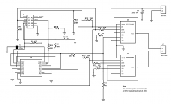
By looking at the original board (4 MOSFETs in H-bridge), I guess it is a single-coil, single-Hall-sensor motor. It makes sense: the blades rotate in random direction, only speed matters.
I cannot understand if DRV8308 is able to drive this kind of motor. I only can connect 2 wires to coils, the third would be unused. Datasheet states it has a 180° drive mode, but it starts in 120° mode then switches to 180° when reaching a configurable speed; I could set an extremely low threshold so it would just start and immediately switch, but it seems in 180° mode waveforms are still over three phases.
Does anybody have experience in such a setup?
Alternatively I could replace the whole motor, but apart from the cost and the throwing away a perfectly fit one, I'm scared of the needed mechanical adaptation to fit a different one...
 
After studying DRV8308 Datasheet, I've concluded it's not done to control a single coil motor.
As I don't want to develop a custom board, I've searched for an already made single coil (or 1-phase) motor controller; but while there are many 3-phase ones, it seems there's none this type. It's a pity- apart from Husqvarna, it seems also Ambrogio uses them, and probably others.
However. after studying a bit more, I've discovered that brushed dual H-bridge motor controller can be used for that; all is needed is to invert polarity of output with commutation of the Hall effect sensor inside the motor. In practice, the "direction" pin should be connected to sensor instead of controlling MCU.
So I'm studying existing controller boards to see which is easier to modify.
Then, if I've understood correctly, I'd simply modify source code to send correct signals to control board (PWM essentially). Also I have to report back odometry signal - probably the Hall sensor output itself.
 
Hi Mumon,

this is really an interesting project. I will follow your posts. I have the same mower (still working) and would like to participate from your experiences. After you succeeded, I think this could be my next winter project. I wish you good luck!

Greetings, Timo
 
I am also interested since I have an 220 AC with a broken motherboard and would like to give it a new and better rebirth.
 
Hi Carsten,
Thanks for your interest; I have designed a controller circuit based on a commercial BTS7960B one, I had to work a bit on it to make it compatible with 3.3 volts logic. I plan to release schematic after testing if it works (if someone is interested, I can send it privately). I still have to finish soldering it, I plan to connect it with an ESP8266 to send PWM signal and read RPM. I'm doing it slowly as I have very few spare time at the moment, but I hope to finish this week.
 
Hi, that sounds very promising. I had taken a quick look onto the Panasonic AN441169, that might be able to drive the motor with some MOSFET-Support, but if you have a bench-working solution - great! Let us go your way to not invent the wheel several times again.
are you able to share some more insights concerning hook-up/setup/parameters-set of the wheel-motors to the DIY-brushless-driver-boards as well as of your mentioned schematic?

I think that would be _very_ helpful, at least to me :) If you like to send it out privately only, i would be very happy as well :)
 

Anhänge

  • AN44169A_E.pdf
    2 MB · Aufrufe: 42
Frankly, I didn't examine the software aspect yet, apart from verifying Azurit has a PWM driver; in my limited experience, I thought a generic one could be enough to generate the needed signals to control the driver. Only needed lines are an enable, and PWM control - a "direction" pin is not needed, as these motors start in a random one each time. As input, I think I only need an ODO to read RPM, plus a "sense" signal only because there's one on BTS7960B (it should warn when current limiting is triggering). I don't know how it is managed on software and if it's useful.
I'm sending you the schematic.
 
Sorry for the long waiting...

I have finally finished to adapt the motor controller, connected it to an ESP8266 with ESP_Easy firmware generating signals (PWM and enable), and tested it; it works perfectly!

The motor runs smooth, exactly as with the original robot board, while I read actual motor speed changing PWM signal.

So, I'd say, goal reached: there's a driver for single coil BLDC! However there's still some work to do.

To drive the motor, I've used a dual BTS7960B motor driver board (also sold by Marotronics), but I had to modify it quite deeply.

In facts, as Carsten pointed out, any brushed H-Bridge driver with a "direction" input pin would work; I didn't find such a ready-made board initially; but Carsten did: the Cytron 13A module. It has no enable and no error/overload out, but maybe that's not a true issue. I encourage anyone to try it, without any need to special modifications: add a pull-up resistor to "DIR" input (suggest 3.3K to +5V), and connect it to motor's built-in Hall sensor open collector output; you can also use it to feed ODO signal, but be careful to reduce it to 3.3V before.

In case you're going for my controller instead, here is the schematic and a few notes.

This (brushed) motor driver includes twin BTS7960 drivers and a 74HCT244 buffer, with separate PWM/enable pins. You can easily find original schematics on Internet, but we warned that, at least in my case, resistor values are different - and I think wrong on my item. I had to replace all of them, plus I had to add many more resistors and modify wiring extensively (and fortunately it's a simple board...); nonetheless, it become a mess of wires and components. I think it won't survive long to vibrations on a real mowing robot, and servicing buried wires is not easy!

bt2.jpg

Instead of raising several 74HCT244 pins and reroute them, maybe it could be more convenient to de-solder the whole chip then re-soldering it on an SO20 prototyping PCB, add there needed components, then connect the new PCB to original IC pads (almost all needed connections are there - notably the IS signals).

20210805_221557.jpg

Anyway, after studying the datasheets, I was convinced that while BTS7960 can be controlled by 3.3V from Arduino, 74HCT won't do: HCT series needs 5V, input and output levels are incompatible with 3.3V. So I've put resistive partitors on its output for Arduino, while no signal from Arduino goes to it.

The Papst BG3612 motor I'm trying to drive has an Hall sensor - it probably is a HAL506, that need at least 3.8V (means: 5V) and has an open collector output. I've verified that the output of the hall sensor switches every 90° turn (two cycles for rev), and the duty cycle is close to 50% (I don't think the motor could run smoothly, or efficiently, if it was significantly different from that).

So here is the design.

Single-Coil-BLDC.png

74HCT244 (U1) is a dual 4-bit buffer with enable. I've arranged enable inputs so that initially the first buffer is disabled (R7 pull up to pin 1), the second is enabled via a pull-down (R11 and R4). An input of first buffer is tied to +5, while its output is connected to 2OE; so, when the Hall sensor pulls down the 1OE and enables the first buffer, the second is disabled and vice versa.

The INH (enable) of both BTS7960 are driven by two 10K resistors (R14, R15) from its external control (datasheet says it is the way to do), while a pull-down resistor (R8) ensures motor is disabled at start; the same for IN (R12, R13, R3) that are controlled by PWM input. However, each IN input is also connected to an output of the HCT244 that are is in a different buffer. So every time the Hall sensor commutates which buffer is enabled, an IN input of one BTS7960 is tied to 0V, while the other receives the PWM signal (this because two buffer's inputs are tied to 0V).

R11-R4, apart from being a pull-down, also work as a partitor to limit to 3.3V the Hall signal, feeding the ODO output.

The BTS7960 also have an IS (current sense) output that also work as an error/limit output. It's an analog signal that easily go beyond 3.3 or even 5V; so I thought to feed it to an input of HCT244 - input is internally clamped to 5.5V, while R10 limits current; then, on its output a partitor (R9, R2) reduces it to 3.3V. However, buffers of HCT244 are off 50% of the time; so I've thought to put two of them in parallel: anytime there's one active to propagate the signal to ERR output. While there could be some nanosecond spikes, I hope these would not make harm - in case, a few pF capacitor could iron them out.

Hope this will help, in case of need write me!
 

Anhänge

  • Single-Coil-BLDC.png
    Single-Coil-BLDC.png
    53,5 KB · Aufrufe: 20
Sorry for the long waiting...

I have finally finished to adapt the motor controller, connected it to an ESP8266 with ESP_Easy firmware generating signals (PWM and enable), and tested it; it works perfectly!

The motor runs smooth, exactly as with the original robot board, while I read actual motor speed changing PWM signal.

So, I'd say, goal reached: there's a driver for single coil BLDC! However there's still some work to do.

To drive the motor, I've used a dual BTS7960B motor driver board (also sold by Marotronics), but I had to modify it quite deeply.

In facts, as Carsten pointed out, any brushed H-Bridge driver with a "direction" input pin would work; I didn't find such a ready-made board initially; but Carsten did: the Cytron 13A module. It has no enable and no error/overload out, but maybe that's not a true issue. I encourage anyone to try it, without any need to special modifications: add a pull-up resistor to "DIR" input (suggest 3.3K to +5V), and connect it to motor's built-in Hall sensor open collector output; you can also use it to feed ODO signal, but be careful to reduce it to 3.3V before.

In case you're going for my controller instead, here is the schematic and a few notes.

This (brushed) motor driver includes twin BTS7960 drivers and a 74HCT244 buffer, with separate PWM/enable pins. You can easily find original schematics on Internet, but we warned that, at least in my case, resistor values are different - and I think wrong on my item. I had to replace all of them, plus I had to add many more resistors and modify wiring extensively (and fortunately it's a simple board...); nonetheless, it become a mess of wires and components. I think it won't survive long to vibrations on a real mowing robot, and servicing buried wires is not easy!

Anhang anzeigen 2796

Instead of raising several 74HCT244 pins and reroute them, maybe it could be more convenient to de-solder the whole chip then re-soldering it on an SO20 prototyping PCB, add there needed components, then connect the new PCB to original IC pads (almost all needed connections are there - notably the IS signals).

Anhang anzeigen 2798

Anyway, after studying the datasheets, I was convinced that while BTS7960 can be controlled by 3.3V from Arduino, 74HCT won't do: HCT series needs 5V, input and output levels are incompatible with 3.3V. So I've put resistive partitors on its output for Arduino, while no signal from Arduino goes to it.

The Papst BG3612 motor I'm trying to drive has an Hall sensor - it probably is a HAL506, that need at least 3.8V (means: 5V) and has an open collector output. I've verified that the output of the hall sensor switches every 90° turn (two cycles for rev), and the duty cycle is close to 50% (I don't think the motor could run smoothly, or efficiently, if it was significantly different from that).

So here is the design.

Anhang anzeigen 2799

74HCT244 (U1) is a dual 4-bit buffer with enable. I've arranged enable inputs so that initially the first buffer is disabled (R7 pull up to pin 1), the second is enabled via a pull-down (R11 and R4). An input of first buffer is tied to +5, while its output is connected to 2OE; so, when the Hall sensor pulls down the 1OE and enables the first buffer, the second is disabled and vice versa.

The INH (enable) of both BTS7960 are driven by two 10K resistors (R14, R15) from its external control (datasheet says it is the way to do), while a pull-down resistor (R8) ensures motor is disabled at start; the same for IN (R12, R13, R3) that are controlled by PWM input. However, each IN input is also connected to an output of the HCT244 that are is in a different buffer. So every time the Hall sensor commutates which buffer is enabled, an IN input of one BTS7960 is tied to 0V, while the other receives the PWM signal (this because two buffer's inputs are tied to 0V).

R11-R4, apart from being a pull-down, also work as a partitor to limit to 3.3V the Hall signal, feeding the ODO output.

The BTS7960 also have an IS (current sense) output that also work as an error/limit output. It's an analog signal that easily go beyond 3.3 or even 5V; so I thought to feed it to an input of HCT244 - input is internally clamped to 5.5V, while R10 limits current; then, on its output a partitor (R9, R2) reduces it to 3.3V. However, buffers of HCT244 are off 50% of the time; so I've thought to put two of them in parallel: anytime there's one active to propagate the signal to ERR output. While there could be some nanosecond spikes, I hope these would not make harm - in case, a few pF capacitor could iron them out.

Hope this will help, in case of need write me!
Is there any way I could contact you about a few questions?
 
Oben