BL-Motore drehen nur via SPI (solved)

jklotzek

Member
Hallo liebes Forum,

Ich habe ein Komplettset aus dem Shop mit PCB1.4, BL-Adapter1.1 und BL-Treibern1.1 (sunray).

Ich ging davon aus, dass die Treiber bereits programmiert seien. Auf dem Päckchen steht "Brushless-motor Driver AM-Mower-Version". Ich bekomme jedoch im log folgende Fehler:
Code:
Error: motor left fault
Error: motor right fault
Error: motor mow fault

Ich habe mir also einen Nano organisiert und die DRV8308_SPI_nano aufgespielt. Kein Erfolg, es dreht sich Nichts. An folgenden Parametern habe ich gedreht (alle Kombinationen), ohne Erfolg:
Code:
#define Reg00 0b1101101101100101   // kk: Bit11 Enable auf 1 Bits45 SPI/PWM
digitalWrite(MotEnlPin,LOW);
SPI.beginTransaction(SPISettings(1000000, MSBFIRST, SPI_MODE0)); // kk: SPI-speed runter

Serieller Monitor des Nano:
Code:
Reg. before initialisation
Reg      Value
Reg.0:  1101001101010101
Reg.1:  11110
Reg.2:  1110110100
Reg.3:  1110100000000000
Reg.4:  10010010010
Reg.5:  11100000000111
Reg.6:  10010110000
Reg.7:  1110110110
Reg.8:  100101100
Reg.9:  1001011000
Reg.A:  11100101100
Reg.B:  0
Reg.2A:  11000
Reg. after initialisation
Reg      Value
Reg.0:  1101001101010101
Reg.1:  11110
Reg.2:  1110110100
Reg.3:  1110100000000000
Reg.4:  10010010010
Reg.5:  11100000000111
Reg.6:  10010110000
Reg.7:  1110110110
Reg.8:  100101100
Reg.9:  1001011000
Reg.A:  11100101100
Reg.B:  0
Reg.2A:  11000

Das sieht für mich so aus, als ob die SPI-Kommunikation arbeitet. Korrekt? Wie gesagt, keine Reaktion der Motore. Der Enable Pin des Drivers ist auf Masse gejumpert, 24V sind da, 5V für die Halls sind da.
Mir gehen jetzt die Ideen aus. Kann mir Jemand bitte auf die Sprünge helfen?

Viele Grüße,
Jürgen
 
Ja und ja. Und wie gesagt: Es geht keiner der drei Motoren.
config.h:
Code:
// ----- gear motors --------------------------------------------------
#define MOTOR_DRIVER_BRUSHLESS   1     // uncomment this for new brushless motor drivers
Ich hoffe, das ist die einzige diesbezügliche Zeile in der config.

Seltsam, aber vielleicht ein Fingerzeig auf die Lösung, ist ja, dass beim Normalstart Nichts passiert, aber auch nicht via SPI über den Nano. Dabei ist der BL Adapter und die PCB ja gar nicht angeschlossen.

Viele Grüße,
Jürgen
 
Hallo,

ist aber auch aktiv:
Code:
// choose ticks per wheel revolution :
// ...for the brushless motor april 2021   https://wiki.ardumower.de/index.php?title=Datei:BLUnit.JPG
#define TICKS_PER_REVOLUTION  1300 / 2    // 1194/2  odometry ticks per wheel revolution

// ----- gear motors --------------------------------------------------
#define MOTOR_DRIVER_BRUSHLESS   1     // uncomment this for new brushless motor drivers

Viele Grüße,
Jürgen
 
The SPI is working this is a good news.

As i saw you REG 0 is
Reg.0: 1101001101010101

It means that the motor is control by PWM

If you want to test your card with SPI control you should change REG 0 by
Reg.0: 1101001101100101
^^
bit 4 and 5 are changed.

After the initialisation you should see that this regsiter is changed.

Then you can try the 's' command

I hope this will work.

If this is ok, we can search more.

Stephane.
 
Dear Stephane,

I already tried changing bit4&5. But there was a very good hint in your post: "Then you can try the "s" command". I remember, that in the BL-DIY manual I read "wait some seconds and the motor will start to turn". This is what I did: Waiting ;-)

I think s stands for stop so again nothing happened. But then I tried "l" and the motor began to turn. So I can confirm, both wheel motors are working properly.

SUCCESS

But I think these parameters are not correct for the mowing motor BL57. Which are the correct ones, do you maybe know?

Best regards,
Juergen
 
Yes it was the 'l' command... sorry...

Good news if your motors are working!

The parameters are the same for the mowing motor and the driving.
I asked Bernds for that.

To be sure I checked my 3 drivers and i can confirm they are the same on the 3 drivers.

The parameters are in the Arduino prog.

So i think your parameters are correct.

I think, now you can check the enable signal and the pwm signal to see if something is changing when you are in the motor test prog AT+E in the command line when connected to the grand central M4 (if i remember correctly)
 
OK, I thought I heard some jamming so I cut off the 24V immediately. But maybe I am wrong, there is the mower plate mounted, so noise can be different.
I will check and try with the PCB later today or tomorrow morning.

But thanks so far, this was a big step ahead.

Best regards,
Juergen
 
Hello Stephane,

confirmed. I hate to say, but yes, by accident I changed two Hall wires. When wiring is correct, the mower motor is running perfectly.
So all motors are working via SPI. This is good news.

The bad news is, when running via PCB I still have these failures "motor fault". Please take a look at the log:

Code:
no SD card found
RESET cause: power-on
Ardumower Sunray,1.0.187
compiled for: Adafruit Grand Central M4
MOTOR_DRIVER_BRUSHLESS: yes
enableCharging 0
trying to detect Bluetooth 4.0/BLE module (make sure your phone is NOT connected)9600...
BLE: AT
trying to detect Bluetooth 4.0/BLE module (make sure your phone is NOT connected)115200...
BLE: AT
OK
Bluetooth 4.0/BLE module found!
BLE: AT+VERR?
HMSoft V610
BLE: AT+NAMEArdumower
OK+Set:Ardumower
BLE: AT+RESET
OK+RESET
SERIAL_BUFFER_SIZE=1024 (increase if you experience GPS checksum errors)
-----------------------------------------------------
UBLOX::begin
trying to connect to ublox f9p...
NOTE: if GPS is not responding either set 'GPS_CONFIG=false' in config.h or perform GPS wire fix (see Wiki)
trying baud 115200
GPS receiver found!
ublox f9p: sending GPS rover configuration...
idx=0...OK
idx=1...OK
idx=2...OK
config sent successfully
sizeof Point=4
map load... no map file!
map dump - mapCRC=0
points:
perimeter pts: 0
exclusion pts: 0
exclusions: 0
dock pts: 0
mow pts: 0
free pts: 0
mowPointsIdx=0 dockPointsIdx=0 freePointsIdx=0 wayMode=3
[WiFiEsp] Initializing ESP module
[WiFiEsp] >>> TIMEOUT >>>
[WiFiEsp] >>> TIMEOUT >>>
[WiFiEsp] >>> TIMEOUT >>>
[WiFiEsp] >>> TIMEOUT >>>
[WiFiEsp] >>> TIMEOUT >>>
[WiFiEsp] Cannot initialize ESP module
[WiFiEsp] >>> TIMEOUT >>>
[WiFiEsp] No tag found
ERROR: WiFi not present
MPU ID=0x0
MPU6050/9150/9250/9255 not found - Did you connect AD0 to 3.3v and choose it in config.h?
resuming is activated
state load... no state file!
Error: motor left fault
Error: motor right fault
Error: motor mow fault
dumpState:  X=0.00 Y=0.00 delta=0.00 mapCRC=0 mowPointsIdx=0 dockPointsIdx=0 freePointsIdx=0 wayMode=3 op=0 sensor=0 sonar.enabled=1 fixTimeout=0 absolutePosSource=0 lon=0.00 lat=0.00
save state... ERROR opening file for writing
temp=998.0  humidity=998 CPU: PTAT=810 CTAT=902 deg=26.13 voltages: I/O=3.37 Core=1.24 VBAT=1.75
0:0:28 ctlDur=0.00 op=0 freem=240679 sp=200015F0 volt=24.34 chg=0.00 tg=0.00,0.00 x=0.00 y=0.00 delta=0.00 tow=305099800 lon=0.00000000 lat=0.00000000 h=0.0 n=0.00 e=0.00 d=0.00 sol=0 age=28.24
ublox chka error, msgclass=1, msgid=12, msglen=24: 0!=80
resetMotorFaultCounter 0
Error: motor left fault
Error: motor right fault
Error: motor mow fault

The used combination is :
Grand Central M4 + BL-adapter 1.1 + BL-drivers 1.1

Any hints?

Best regards,
Juergen
 
Jürgen,
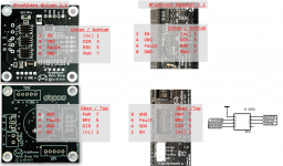
we want to insure, that everything is fine with Code concerning PWM frequency comming fm. Arduino. See Picture to lacte PWM-Pin.
After many failed attempts, I decided to remove the pinman code at my personalized Azuri tand instead make the necessary PWM settings directly in variant.h. No idea if this is best practice, but since then my motors are running

Best regards, Rolf
1631123374615.png
 
Der Norman,
OK understood where to measure. What shall be the result of the measurement after booting of M4 has finished?
Should I send "AT+E" before measurement to start an odometry test?

Best regards,
Juergen
 
Zuletzt bearbeitet:
Hi Juergen

According to me, when the M4 is booting all the mortor are not runnig.
Then the M4 checks the 3 errors line and if it sees 1 (or 3) errors it writes them on the console..

If the 3 errors are poping up, it means that the M4 sees 3 errors!

I don't think the errors comes from the drivers because the 3 drivers seems to work by SPI.

So, the error can come from the BL Adapter or the ribbon connectors.

Do the connectors have the right orientation? You may have by mistake solderer them rotated 180°?
Check the error signal on the board. It sould be 3.3V : no fault.


Stephane.
 
Dear Stephane,

I measured the fault line Pin6 on the Driver board: 0V. Regardless if connected or not. Pin6 on adaperboard is 0,25V if unplugged.

I can see some pull-up resistors on the adapter-board in the picture of Rolf. I did not solder them because I read no bug-fix needed in the combination of PCB1.4+adapter1.1+driver1.1. Are they needed? Are they a pull up to 3.3V (no fault)?

Best regards,
Juergen
 
HI,

Could you try to lauch the AT+E command with the M4
It is the motors test command.

I look at the source code, and it seams that this test does not check the error pin.
So it could be interresting to see if the motors run with this test.


Stephane.
 
Dear Stephane,

no, the motors do not turn. Please see the log:
Code:
...
resetMotorFaultCounter 43
ERROR: motor recovery failed
Error: motor left fault
Error: motor right fault
Error: motor mow fault
CON:AT+E
motor test - 10 revolutions
t=0  ticks Left=0  Right=0  current Left=0.11  Right=0.13
t=1  ticks Left=0  Right=0  current Left=0.10  Right=0.08
t=2  ticks Left=0  Right=0  current Left=0.11  Right=0.10
t=3  ticks Left=0  Right=0  current Left=0.15  Right=0.11
t=4  ticks Left=0  Right=0  current Left=0.10  Right=0.11
t=5  ticks Left=0  Right=0  current Left=0.14  Right=0.10
t=6  ticks Left=0  Right=0  current Left=0.14  Right=0.13
t=7  ticks Left=0  Right=0  current Left=0.13  Right=0.09
t=8  ticks Left=0  Right=0  current Left=0.11  Right=0.13
t=9  ticks Left=0  Right=0  current Left=0.13  Right=0.06
t=10  ticks Left=0  Right=0  current Left=0.13  Right=0.13
t=11  ticks Left=0  Right=0  current Left=0.14  Right=0.09
t=12  ticks Left=0  Right=0  current Left=0.13  Right=0.11
t=13  ticks Left=0  Right=0  current Left=0.11  Right=0.13
t=14  ticks Left=0  Right=0  current Left=0.15  Right=0.13
t=15  ticks Left=0  Right=0  current Left=0.13  Right=0.09
t=16  ticks Left=0  Right=0  current Left=0.10  Right=0.08
t=17  ticks Left=0  Right=0  current Left=0.13  Right=0.09
t=18  ticks Left=0  Right=0  current Left=0.11  Right=0.10
t=19  ticks Left=0  Right=0  current Left=0.13  Right=0.11
t=20  ticks Left=0  Right=0  current Left=0.13  Right=0.06
t=21  ticks Left=0  Right=0  current Left=0.10  Right=0.10
t=22  ticks Left=0  Right=0  current Left=0.14  Right=0.11
t=23  ticks Left=0  Right=0  current Left=0.11  Right=0.09
t=24  ticks Left=0  Right=0  current Left=0.16  Right=0.11
t=25  ticks Left=0  Right=0  current Left=0.11  Right=0.09
t=26  ticks Left=0  Right=0  current Left=0.10  Right=0.08
t=27  ticks Left=0  Right=0  current Left=0.13  Right=0.08
t=28  ticks Left=0  Right=0  current Left=0.15  Right=0.10
...

Just one question: How can I be sure, the drivers are programmed? And what would happen, if they are not?

Best regards,
Juergen
 
Oben