Assembled but connecting the battery - blows the EF2 fuse

hotchiguy

New member
Hello,

I have just finished the kit assembly (brushless motors, GPS RTK)
After I've connected all the components to the board, I've plugged in the battery but nothing turned on.
I found out that EF2 wasn't conducting anymore, so I replaced it and re-plugged everything - I saw a short blink of the 24V LED but then the fuse was blowned again :((

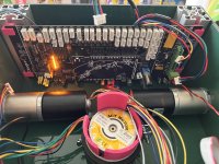
I've re-soldered new fuse. I can power up the board with Arduino, 9V regulator just fine - see the attached picture.
Seems like whatever left to connect - such as motors, motor driver, gps, esp32, ultrasound sensors - causing a short circuit.

I would really appreciate if anybody has an idea on what is likely the cause or how can I test individual connections without keep blowing the fuses - I only have few more left.
 

Anhänge

  • IMG_5764.jpg
    IMG_5764.jpg
    3,2 MB · Aufrufe: 16
Before you check on my suggestion: I am not very sure... But I see that all connectors on the Board are the same way. Check if + and - for Modules is absolutely right?
Some of my Board are flipped, but it could be my fault on soldering. Did you tripple check + and - with every Module (3.3V or 5V) connection is ok? Are the Modulepullupjumpers right for 5V or 3.3V
On first try, i did destroy the HTU Sensor becouse i miss connected it. Luckily, nothing else was burned.

On a closer look, i dont see PullUp Jumpers?!
 
Zuletzt bearbeitet:
Before you check on my suggestion: I am not very sure... But I see that all connectors on the Board are the same way. Check if + and - for Modules is absolutely right?
Some of my Board are flipped, but it could be my fault on soldering. Did you tripple check + and - with every Module connection is ok?
On first try, i did destroy the HTU Sensor becouse i miss connected it. Luckily, nothing else was burned.
I checked the polarity of the motors cables - I replugged the cables for one of the motor drivers that looked like it had a bit of exposed cable.

Checking the brushless components diagram - YIKES!!! The + and - are reversed from board labels and standard components.
Is this right?

1652731584464.png
 
I think i followed this picture and found it arkward too. But i did it so. I can check if you like, but waiting for another user might be good too.
Its raining, but wait some minutes. I will take a look at my cables.

If it was flipped, maybe wait for some expert oppinion before reconnecting it the right way. Maybe something burned and protected your board/adapter board this way and reconnecting it the right way could burn something else.

On the other hand, a flipped terminal causing the main fuse would make sense. In the way + was connected to ground.

What driverBoard version is it?

I just checked and realised its the mainboard.
Mine is definitly connected like the picture. Thats the fault.
 
Zuletzt bearbeitet:
Yeah the pictures is correct, the 3 motor ports are different to the rest.
And yes that is kind of strange, don't know why it's designed that way. :rolleyes:
 
I think i followed this picture and found it arkward too. But i did it so. I can check if you like, but waiting for another user might be good too.
Its raining, but wait some minutes. I will take a look at my cables.

What driverBoard version is it?
Mr. Tree, looks like I had my power cables reversed after all. eRacoon confirms it as well.
I am going to reconnect everything correctly and will post here soon if that solves the issue.
Thanks for you help!
 
Glad we could help. Thanks.
I am giving you thumps that everything still works!!
 
Zuletzt bearbeitet:
How would you remove the soldered fuse is my question specifically. I’m assuming you’d heat the solder joint on each end of the ef2 fuse while trying to remove it. Do you have any details on what fuse type we would use to replace it? Any advice here would be appreciated.
 
I’m assuming you’d heat the solder joint on each end of the ef2 fuse while trying to remove it
More or less it was my way
Do you have any details on what fuse type we would use to replace it?
Copied from FAQ
Welche Sicherungen sind im PCB 1.4 verbaut? Which fuses are installed on the PCB 1.4?
Es handelt sich bei allen Sicherungen auf dem PCB 1.4 um Träge Varianten. F1 = T6,3A (Sicherung hinter dem Spannungsregler U1 für die 9V DC) Anmerkung: Wenn keine T6,3A verfügbar ist, würde ich eine T5A einsetzen. EF1 = T3A (Sicherung hinter dem Ladeanschluss P42.(Ladestromsicherung)) Anmerkung: Wenn die Lötbrücke JP16 für den erweiterten Messbereich von 5A geschlossen wird, um ein leistungsstärkeres Ladegeräte zu verwenden, muss unter anderem die Sicherung EF1 angepasst werden. In diesem Fall würde ich eine T6,3A nehmen. Zusätzlich muss in der config.h folgende Zeile aktiviert werden: #define CURRENT_FACTOR 2.941 // PCB1.4 (bridged INA169, max. 5A) EF2 = T6,3A (Hauptsicherung hinter der Batterieeinspeisung max. T10A) Anmerkung: Wenn keine T6,3A verfügbar ist, würde ich eine T7A einsetzen. EF3 = T1A (Versorgung von P16 (RPI Backup Power). Sicherung geht ebenfalls direkt von der Batterieeinspeisung P43 ab und kann Module versorgen, die auch nach der Unterspannungsabschaltung des Boads mit Spannung versorgt werden sollen. Achtung! Dadurch besteht die Gefahr der Tiefentladung des Akkus.) Passende SMD-Sicherungen und Sicherungshalter gibt es z.B. bei Reichelt von der Firma Littelfuse. Hier die entsprechenden Links: ————————————— Komplett mit Halter: T1A = Artikel-Nr.: LITT 0154001.DRTSMD-Sicherungshalter, mit Sicherung 1,0 A, 125 V, träge T3A = Artikel-Nr.: LITT 0154003.DRTSMD-Sicherungshalter, mit Sicherung 3,0 A, 125 V, träge ————————————— Ersatzsicherungen: T1A = Artikel-Nr.: LITT 0452001.MRLSMD-Sicherungen, MELF 6125, träge, 1,0 A, Serie 452 T3A = Artikel-Nr.: LITT 0452003.MRLSMD-Sicherungen, MELF 6125, träge, 3,0 A, Serie 452 T5A = Artikel-Nr.: LITT 0452005.MRLSMD-Sicherungen, MELF 6125, träge, 5,0 A, Serie 452 (Für EF1) T7A = Artikel-Nr.: LITT 0452007.MRLSMD-Sicherungen, MELF 6125, träge, 7,0 A, Serie 452 (Für EF2)
 
Oben