Ardumower pcb 1.2 build

royalann

New member
Hi all,

Working my way through the build of the ardumower pcb 1.2. See pictures below.

I have some questions however:

1.) How do I connect the Bluetooth chip to the pcb? There are duplicate ports on the pcb, which ones should I use? See close up pictures below(IMG0296.JPG).

2.) Anyone got pictures of how the wheel motors and cutter motor are wired to the motor driver chips and battery? This is very confusing for me.

Thanks in advance.
Paul
 
Leider ist mein Englisch sehr schlecht. (Übersetzung mit google Translate) Die Anschlüsse für das Bluetooth Modul sind in 2 verschiedenen Versionen ausgeführt. Das hat den Grund das es die BT Module mit verschiedenen Anschlussbelegungen gibt. Deshalb sind 2 Lochreihen vorhanden. Bitte nur die Lochreihe verwenden die mit dem BT Modul übereinstimmt. Bitte auf keinen Fall beide Lochreihen gleichzeitig verwenden.
Gruß Uwe


Sorry my English is very bad. (Translation by Google Translate) The connections for the Bluetooth module are executed in 2 different versions. This has the reason that there is the BT modules with different pin assignments. Therefore, 2 rows of holes are present. Please only the row of holes using matches the BT module. Please never use both rows simultaneously.
greetings Uwe

Dokumentation zur Zeit leider nur auf Deutsch
Documentation currently only in German https://github.com/Ardumower/ardumower/tree/develop/Dokumentation
http://www.ardumower.de/index.php/de/forum/ardumower-platinen/560-ardumower-board-aufbau-anleitung
 
Hi all
I finish to assemble my PCB v1.2 and it's work very well.
Here some very small remark concerning assembly or modif for a futur version of this pCB.

Note i order all part in Maratronic shop.

If you need to test motor or sensor or modify the soft using the arduino console maybe it's better to not solder the part for charging battery because there are too near the USB cable or you need a special USB connector or maybee Arduino Due.
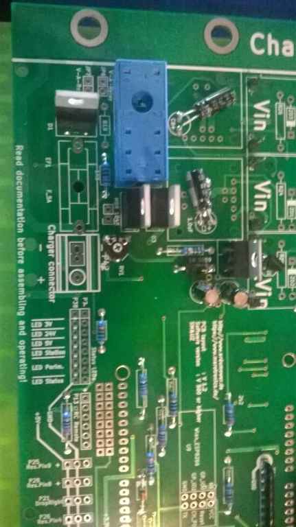
It's concern the D3 diode , U3 and relais socket.
See
WP_20160619_002.jpg


Do not forget to add this composant after your test.


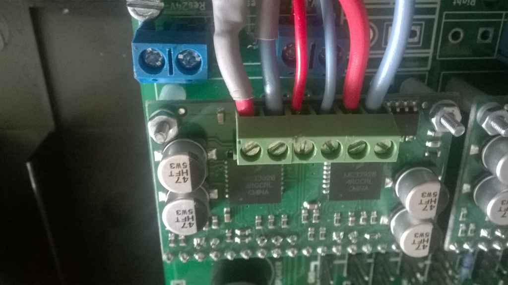
I don't know why but the space in the OUT of DC DC converter and MC33926 are not 2.54 so you can't use standard plug and need to adapt if you want to make it removable .
For DC DC converter it's good security , so you can't solder it in bad position but for Motor ???


WP_20160603_007.jpg


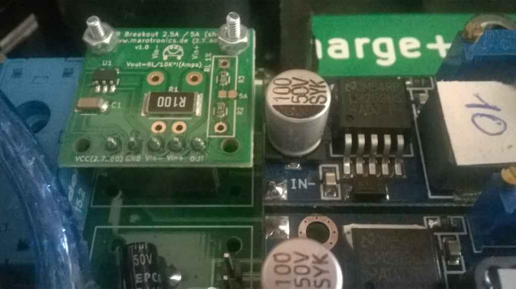
For U3 and U5 maybe it's better to solder the C3 and C6 at the rear of the PCB so not like in this picture:

WP_20160603_005.jpg


In MC33926 there are 7 slot on PCB but Nothing connected so maybe it's not necessary to use it for me it's work whithout.
Like for the DC DC converter the space of power pin are not 2.54 standard so if you want to make this board removable please adapt as your way.


WP_20160615_007.jpg


WP_20160619_003.jpg


WP_20160619_005.jpg


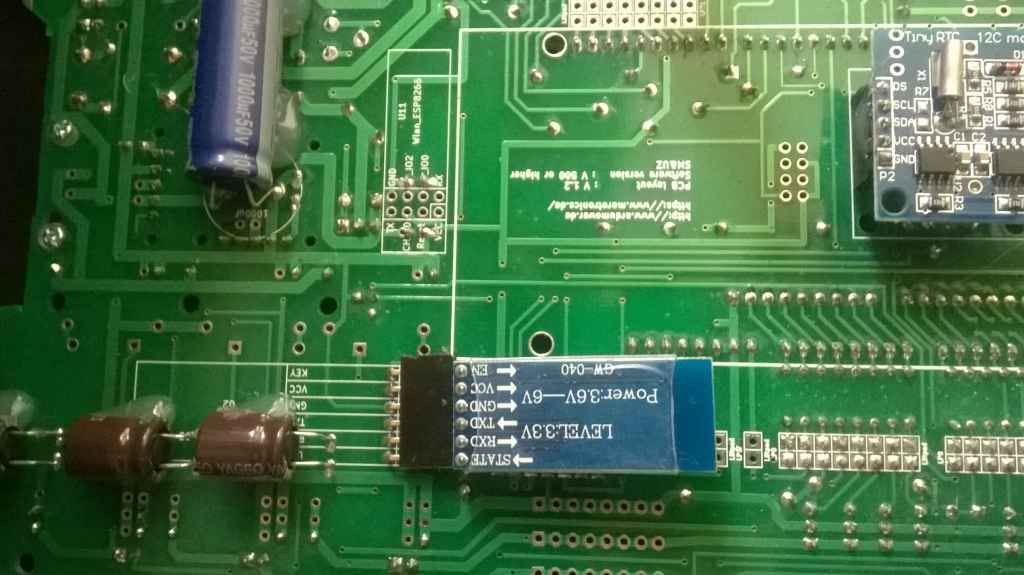
Connecting the HC05 module 2 possibility.
This one works after setting the correct baudrate.


WP_20160617_001.jpg


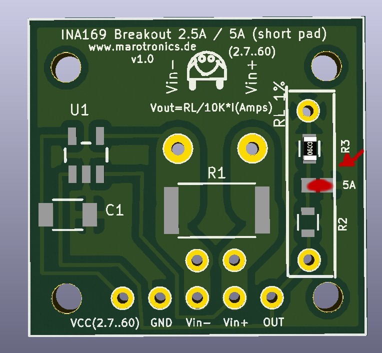
INA169 U3 or U5 I solder only the 5 plug and use screw on the opposite side for fixe it

WP_20160619_006.jpg


I think all this remark are for 06/2016 composant and maybe the DC/DC converter or MC33926 or INA169 have different version.

Now i need help for the LED there is Nothing in WIKI and i don't understand how to connect them but it work whitout and whithout charging station I view that there is one needed for charging ?.


I finish whithout understand German Note and very satisfy of this Board.

Thank you and congratulation for all working on this project
Attachment: https://forum.ardumower.de/data/media/kunena/attachments/3545/WP_20160619_002.jpg/
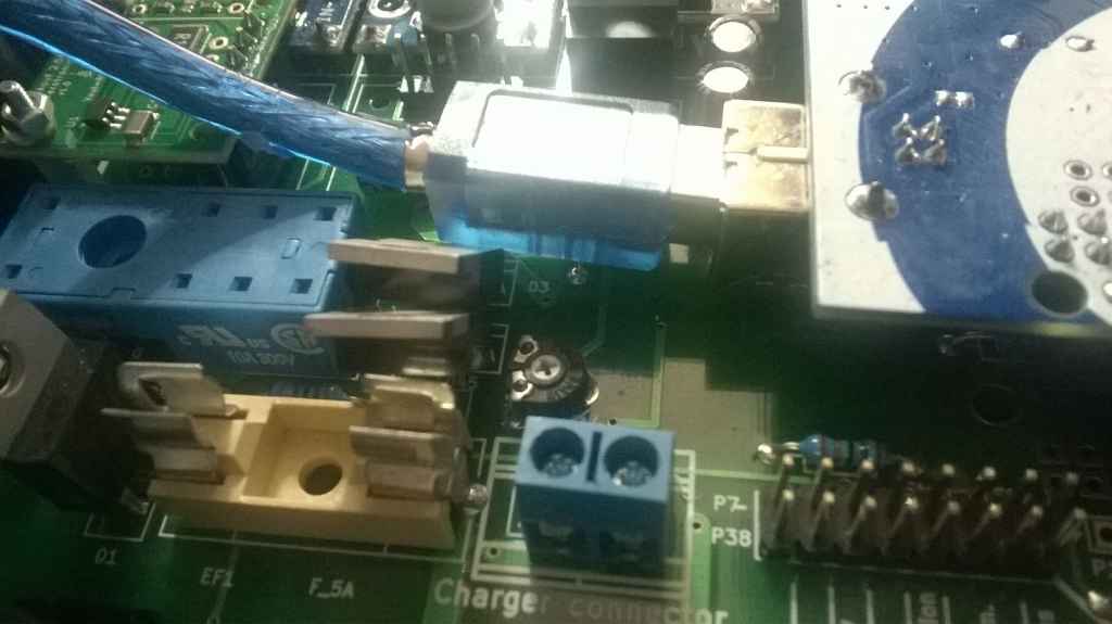
 
Zuletzt bearbeitet von einem Moderator:
Hello again

I looked at your photos, while I made a small mistake is noticed.
The INA169 from the shop has 2 measuring ranges. 2.5A and 5A
On the board of the measuring range 5A is needed.
this needs to be closed to the INA board a small bridge
see photo


INA169.jpg


You mean the station Led?
You need a best LED yellow
You may cast this LEd on the board, a solder or extend and installing into the housing of the Mower.
This indicator to light when applied a voltage to the charging contacts. Then it's right
See photo


StationsLed.jpg


greeting
Uwe

----------------------------------------


Hallo nochmal

Ich habe mir deine Fotos angesehen und dabei ist mir ein kleiner Fehler aufgefallen.
Der INA169 aus dem Shop hat 2 Messbereiche. 2,5A und 5A
Auf den Bord wird der Messbereich 5A benötigt.
dazu muss auf den INA Board eine kleine Brücke geschlossen werden
siehe Foto

Du meinst die Stations Led?
Du brauchst eine LED am besten gelb
Du kannst diese LEd an der Platine ein löten oder verlängern und ins Gehäuse von den Mower einbauen.
Diese Diode muss leuchten wenn an den Ladekontakten ein Spannung anliegt. Dann ist es richtig
Siehe Foto

Gruß
Uwe
Attachment: https://forum.ardumower.de/data/media/kunena/attachments/1259/INA169.jpg/
 
Zuletzt bearbeitet von einem Moderator:
Thank you very much.

I'm going to closed the 5A on the INA169.

For the Led Now i understand with your picture, it's more clear than on the board.

Thanks again.
 
Hi Uwe,
Hi all,

During the last days I soldered PCB 1.2 and have the following questions:
Inden letzten Tage hatte ich beim Bestücken von PCB 1.2 noch folgende Fragen:

1.
If R19 is not needed for 24V-Relais one proposal was to insert a diode instead. Which type of diode is required?
Da R19 als Vorwiderstand bei 24V-Relais entfällt, lautete ein Vorschlag, dort eine Schutzdiode stattdessen einbauen. Welcher Diodentyp ist erforderlich?

2.
Should the real time clock be inserted?
Wird der RTC bestückt oder nicht?

3.
Encoder for mower motor: would it be possible to use the mini encoder (12cpr) from Marotronics shop?
Kann als Mähmotor-Encoder der Mini-Encoder aus dem Shop (12cpr) benutzt werden?


Thanks in advance for your hints
Vielen Dank im Voraus für Eure Tips

Peter
 
... Another open point:
.... Und noch ' ne Frage:

4.
Diode D2: to be or not to be?
Muss D2 eingebaut werden? Wenn nein, stattdessen Brücke?

Now I am nearly clear to test the assembled board :)
Heute Abend noch erster Test? :)

Gruß
Peter
 
Hallo Peter

1. z.B eine 1N4148 oder ähnlich

2. wenn du möchtest das er mal automatisch an bestimmten Wochentagen und Uhrzeiten starten soll ist der RTC notwendig.

3. wenn du den Motor aus dem Shop hast dann eigentlich nicht. Der macht ca 3000 1/min Umdrehungen was gut passt. Ich selber benutze dort auch kein Drehzahlmesser weil die auszulösenden Interrupts die Prozessorauslastung negativ beeinflusst und bei ca 3000 Umdrehungen keine Regelung nötig ist.

4. D2 wird eigentlich nicht gebraucht weil er als einfacher Überspannungsschutz gedacht war für den Mähmotor als es die Protektorboards noch nicht gab.
Ich würde daher eher auf 2 Protektorboards setzen deren Schutz wesentlich umfangreicher bzw besser ist. ( für den Mähmotor und den Antrieb. Gerade wenn du auch mit 24V arbeiten tust.

Gruß
Uwe
 
ok Uwe vielen Dank.

Auch für das Board-Layout, es erscheint mir z.B. von der Beachtung der Rastermaße der JP- und P-Pins viel besser als das V0.5-PCB: man steckt ein paar 3er, 4er und 5er Stiftleiste, eine Buchsenleiste quer drüber und zack-zack ist die Geschichte sauber verlötet. Hat echt Spaß gemacht.

Ich habe mir übrigens erlaubt, Deine PCB 1.2 Anleitung etwas für mich aufzuarbeiten. Ist noch nicht fertig, ich versuche es am Wochenende zu schaffen und die dann mit dem 2. V1.2-Board, das ich noch liegen habe durchzuspielen, um zu sehen, wo noch Lücken sind. Wie gesagt, ist für ursprünglich für mich gedacht. Wenn es Sinn macht, stelle ich sie hier ein und übersetze sie auch gern noch in Englisch.

Habe auch eben mal mein gestern eingetroffenes Ardumower Chassis zusammengebaut. Genial einfach und stabil!!! Als Anleitung habe ich die von Thomas aus Schweden benutzt. Toll gemacht ... die Anleitung, das Chassis, die Elektronik ... einfach alles. Ein Super Projekt. Habe schon viel Spaß und Erfolgserlebnisse damit gehabt :) Langsam lassen die Lästereien in der Familie nach!

Danke an das Ardumowerteam und die vielen Supporter, die ihr Wissen und ihre Fähigkeiten hier zusammenwerfen!!!

Ein schönes Wochenende ...

LG Peter
 
Oben