Arctic Hare Bumper

paddy

Active member
Hello to all,

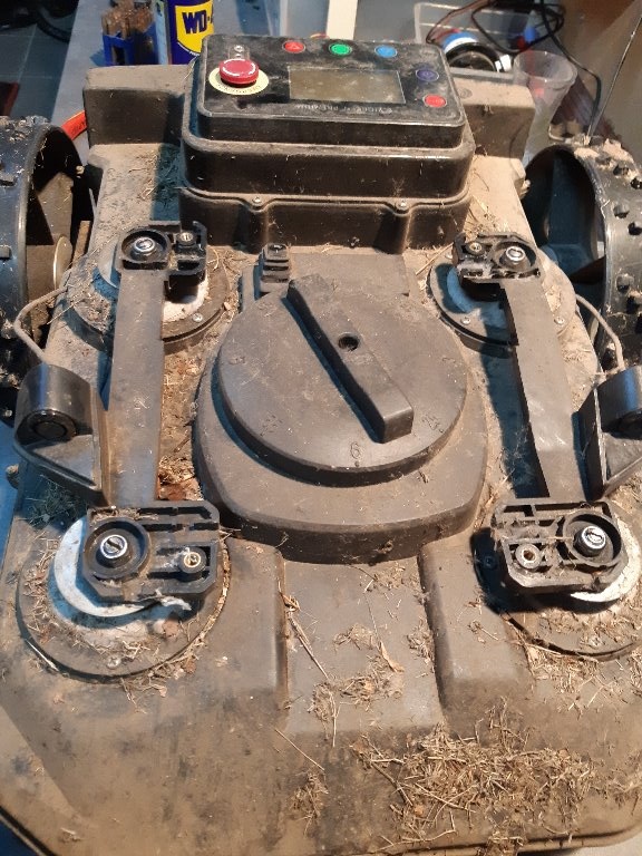
recently, we made some progress on this chassis and im my opinion, most problems seems to be solved. But there is at least one big issue I want to discuss here instead on my build thread because I think, it will be relevant for everyone.

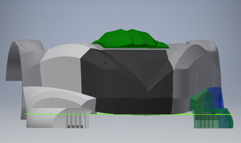
One think totally missing on this chassis design is the bumper. I can't find any information about how this should be implemented and also in Fusion files, there is no answer about this. For me, I want to use the complete chassis as bumper and want to get rid of small bumper areas which in some cases will not be hit even the robot collids with an obstacle.

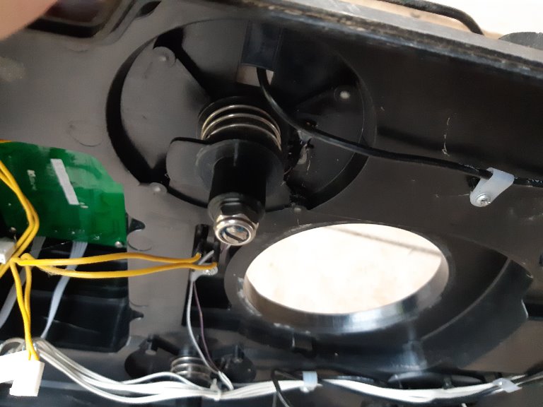
The chassis should be mounted on some kind of rubber dampers. I don't know how rigid they are (Shore), but these parts must be flexible enough to move the body. Also, they must be rigid enough to bring the chassis back in position and also to avoid a shaking body on rough terrains. I'm not sure if the dampers of the shop will solve this, but we can print them out of flexible filaments in any strength and also can mold them with silicone.

Most important for me is, how to discover if body is displaced, aka collids with an obstacle. Im my opinion, there are different solutions

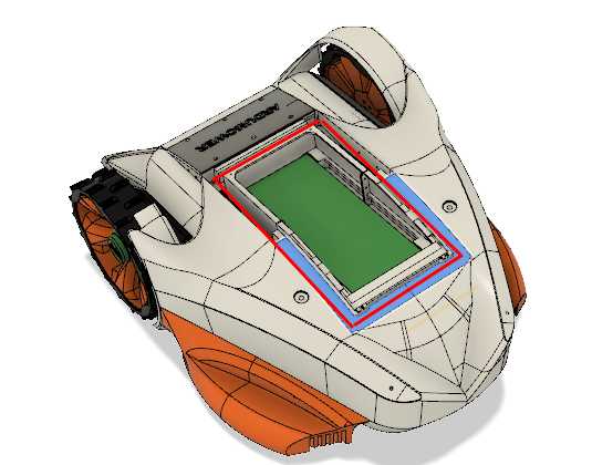
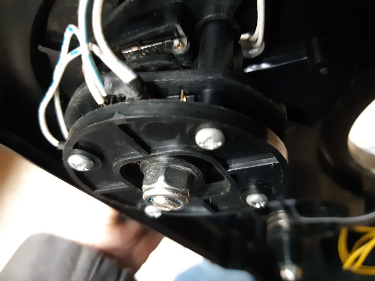
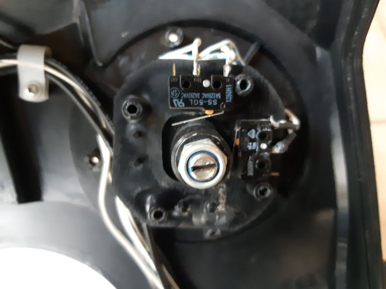
- monetary swichtes/micro switches close to the body (on PCB Box for example). They get pressed by body
- multiple hall sensors to detect a glued magnet. If it is outside a definded offset, it triggers the bumper (can be solved by ATTINY or other without changing Ardumower code)
- Reed switches which are generally closed by a magnet and opens when magnet moves away
- Bumperduino, tube around PCB Box, chassis will compress the tube and triggers event

What do you think, is the best solution here? In my opinion, magnets are best but it is not easy to set zero point for offset detection. Also they may influence perimeter receiver and compass. So it is important to find a proper place for them.
Bumperduino might work but I find this is a expensive solution and I don't have any experience with this so far.
Switches are the most easy solution but they need to be protected carefully from dirt to work.

Patrick
 
I'm working with artic hare also. I don't like rear dampers be in the holes, those are like wells or sewers leading to motor box. Second thing is that dampers are attached to quite large and thin lid. I don't solution yet for dampers, any ideas?
Is it possible detect hits with acceleration sensor?

Bumper duino hose should be like sketched circle on pictures, can it be so low?

bumper1.png

Attachment: https://forum.ardumower.de/data/media/kunena/attachments/4741/bumper1.png/
 
Zuletzt bearbeitet von einem Moderator:
Hi Paddy.
I want to use the complete chassis as bumper
I have a tianchen S520 mower with this kind of bumper.
If you are interest i can remove the top of the mower and send you some picture for idea (If i remember it's not really complex and use only switch and spring).

magnets are best but it is not easy to set zero point for offset detection
100% agree with you

Bumperduino might work but I find this is a expensive solution
100% agree with you


I'am new in 3d printing and know nothing on flexible filament But is it possible to create a kind of bumper like on the RL1000 mower with only 2 metalics part contacting when bump( need flexible part printed). https://www.ardumower.de/index.php/de/forum/your-projects/911-denna-plattform?start=40#10751.
And finally i have on my denna platforrm 2 sonar ,3 laser sensor and bumper and i need to test during the next summer if the bumper is never contact during more than 100 mowing hours.
If it's work ,you don't need Bumper simply no contact sensor B)


Be carrefull also when add the bumper to think on the next step (Charging Station)

Good luck and again congratulation for all your work.
 
I agree, there is a need for simple but effective bumper.
I am inclined to use switches that would sense cover movement against main chasis and some sort of damper.
The rubber dampers from the shop are pretty stiff, so I doubt they will work. Some stiffer spring maybe instead of dampers?
The spring and longer bolt themselves could act as conductor-switch (bolt in the middle would touch the spring).

AFAIK (based on info from spare part list) Husqvarna uses joystick(?) type of sensor to sense upper cover movement in addition to other sensors.

Pressure/weight sensors might work, but I'm wondering regarding false-positives caused by patches of taller grass, which would push the cover just slightly.

Regarding using other sensors (US, laser), I am in doubt. Last summer I used ardumower without bumper with 3 US sensors.
One thing I can tell is that there are so many edge cases in a real environment, where those won't work: angle, small gaps in the fence, poor reflection and so on. Lasers would have helped, but I'm pretty sure - not always.
On the other hand, engine feedback, GPS can help detecting if the mower is stuck ... so, I survived without bumper, but I definitely want to have something for the next summer :)

I like the rubber-wire sensor idea, but as much as I have seen printing flexibles is a bit complicated thing. Never tried printing flexibles myself, but my initial thought is that it might be too complicated.
 
Hello Jussip,

I don't like the Bumperduino because the tube can only cover a small area. If an obstacle is higher than the tube, it will not be detected. My Tianchen uses a small area too and it hits often trees, children's playground and others and don't recognize it. Also accelleration sensor is not adequate in my opinion as it always bumps on grass.

Bernard, it would be great if you provide some pictures. As far as I know, Automower uses Hall sensors whith magnet mounted on a think which looks like a joystick. I think this is a good option but it is not as easy to implement as it sounds. Thanks for the hint with charging station. I always had issues with the initial charging contacts on Tianchen chassis as they are mounted on bumper. But this could be solved by code (eg. if bumper gets hit during perimeter track, first check if contact to charger exist before reverse)

The idea of printing some kind of band-switch with flexible filament, I did some tests last season. See my other build thread "Paddy's mower". I solved it but it was never outside, so I don't know if they work for long time. Also it is not that easy to build.

In my opinion, best bed will hall sensors (3 of them in a circle, or just 2) to detect a magnet. If we use linear hall sensors, we can use trim potis (to adjust offset) and voltage comparator (to trigger). I will try it this way.
 
Hi, I have used Bumperduino with a "D" shaped foam rubber around the original chassis for two years. It was easy to build and highly reliable (Many thanks to Jürgen for the design and the documentation!!!)

The only problem I had was the adhearing of the foam rubber. After some time parts of the bumper sheared of and I had to fix it with cable ties. It stopped looking nice but the bumper was still functional.

My idea is to print a rectangle shaped tube with Filaflex and use it as a sensor AND elastic element between the chassis and the outer shell.
For the attachment of the outer shell I will make two flexible tubes around the mower, one at the height of the bottom plate and one at the height of the ceiling plate. The outer shell can consist of plates that are firmly mounted to both flexible tubes but are not connected firmly to each other (like fish scales).
An obstacle would hit one of the scale plates and compress the tubing below.
I have attached a picture from the design draft with the elastic tubing set to 50% opacity.

An outer shell made of one piece needs to be heavier in order to transmit the movement to the hall sensor and It will make complex movements depending on the angle of the abstacle. It easier to split the outer shell in smaller parts and have the sensor below each of the scale plates.
This should work for the original chassis as well as for arctic hare.
Attachment: https://forum.ardumower.de/data/media/kunena/attachments/3847/sandwitch_bumper.jpg/
 
Zuletzt bearbeitet von einem Moderator:
Hello,

thank you for the hint with the self-adhesive foam-tubes. I assume you mean the ones used to make your door and window air-tight, somethink like these? https://www.ebay.de/i/112025619490?chn=ps&var=410962344859
I didn't know they will work with Bumperduino, but it sounds like a good idea. If you attach them between the chassis and the PCB Box, you may be done. This may be the easiest solution for everyone with Bumperduino. If this device really works that great (never tested), it's time to get one. This will be my plan B, if hall sensors don't work. In my opinion, Bumperduino is pricely but I know that the pressure sensors costs a lot

May you share a picture of your solution? I'm interested how you attached the pressure sensors to the foam tube
 
The foam tubes were suggested by Roland
Forumlink
I have used 21x17mm, the one you have linked is smaller but is also much cheeper. For the outside bumper the big size had an advantage of bigger area, for your purpose the small tube should be sufficient.
I have followed the solution of Roland and sticked a Gardena connector into a small hole of the foam tube (but you could use any small plastic tube for it). It was not really necessary to seal it with glue, just the elastic force of the foam tube around it was enough. I had only to make sure that the connector is not pulled out during the movement of the mower. I did not glue the ends of the tubes as well, i just screwed through the ends of the tube to the chassis (with a big washer disc) so that the holes were closed.

The pressure sensor might be expensive (and the foam tubing was very expensive as well!) but it made it very easy to get a reliably working bumper in a very short building time (as intended by Jürgen). If you have devided your chassis in two independent parts already (PCB Box / outer chassis???), then just placing the foam rubber tubing inbetween might work straitaway.

I can not make pictures of my solution: i have disassabled it in oder to upgrade it with 3d printed parts. But Roland and Jürgen have many posts showing their designs.
 
Hi paddy.
Here the picture .
All the plastic parts can be 3D printed without particular issue.
The most complex to include is the size of each pad.

On the front left 3 switchs (2 for X,Y and one for Z)
On the front right 2 switchs (only X,Y detection)
Rear right and left 1 switch on each. (Z detection)

The mower cover move between 1 and 2 cm on Z axis (detected by 2 rear switch and the one on left) and from X and Y also detected by the 4 switchs on front pad.

This bumpers work really very well


000.jpg

Attachment: https://forum.ardumower.de/data/media/kunena/attachments/3545/000.jpg/
 
Zuletzt bearbeitet von einem Moderator:
Thank you so much Bernard for these detailled pictures and the work you had to disassemble it.

Now we have lots of inspiration how we can solve the bumper as moving chassis:

- simple switches like you've shown
- Hall sensors like Automower does
- Bumperduino with tubbing around the PCB box (see red lines on picture).
bumperduino.png


Because I don't already purchased Bumperduino, I ordered some hall sensors and I've some switches laying around. I will give these a try and if nothing works, I'll try Bumperduino. As I saw in some Videos, it is really sensitive and reacts incredible fast by nearly no pressure. Impressive. So I would assume, if someone builds this chassis and already use Bumperduino, stick to it!
Attachment: https://forum.ardumower.de/data/media/kunena/attachments/2946/bumperduino.png/
 
Zuletzt bearbeitet von einem Moderator:
Hi Bernard,

thank you for the pictures. Unfortunately I miss some information, because I can't see how it is build together.

On the top I see the shaft with the spring. But what is this for a plate then and how looks like the hole of the plate?

On the bottom I see switches. That I understand.

Then on the bottom comes the activator for the switches and then a spring.
After this I see the picture with the bottom shaft and then the last picture is the complete shaft with a groove and then a cone.

So the missing part is, how is the shaft installed through/in the hole and for what is the cone. Can you maybe do a video how this is build together when you disasamble this?

Are the front holder and back holder different?

Thank you very much
Roland
 
I try to receate exactly the same part on Fusion360 and send you the file so you can build one , see how it work and if you want adjust the size to fit in the new chassis.
 
Hi
On the top I see the shaft with the spring. But what is this for a plate then and how looks like the hole of the plate?
I try to make a video but it's not easy.
The hole on the mower case are 11.5 mm diam and the axe is 10mm so the axe move not only up and down but can also inclinate a little the cone help to center all.

The rear 2 pad are use to detect a push on the cover using vertical switch.
70.jpg


All pad use exactly the same part but on the rear the is no switch inside the mower case.

90.jpg


On front another vertical switch detect a pull on the cover:

92.jpg


And the 2 last horizontal switch are used to detect bump

100.jpg


By.
Attachment: https://forum.ardumower.de/data/media/kunena/attachments/3545/70.jpg/
 
Zuletzt bearbeitet von einem Moderator:
Hi Bernard,

thank you very much for your pictures. But how is the shaft hold in the middle? And how is it assembled there ? Where lie the springs on? Where is the cone positioned?
Maybe you can make a small sketch by hand and show this. Currently I have no clue.

Thanks
Roland
 
Oben