Hi,
(Deutsche Version unten)
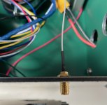
When attaching the antenna cables to the standard chassis, the outside of the antenna cable screw connects with the metal (conductive). If you attach multiple antenna's (XBee and WiFi) to the chassis, this means these antenna's are connected. Somehow, I don't think this is a good idea but I don't know much about antenna's.
Does anybody know and how did you mount your antenna's to the chassis?
----
Beim Anbringen der Antennenkabel am Standardchassis verbindet sich die Außenseite der Antennenkabelschraube mit dem Metall (leitfähig). Wenn Sie mehrere Antennen (XBee und WiFi) an das Chassis anschließen, bedeutet dies, dass diese Antennen verbunden sind. Irgendwie halte ich das für keine gute Idee, aber ich weiß nicht viel über Antennen.
Weiß jemand wie du deine Antenne am Chassis befestigt hast?
Vielen dank
Johan
(Deutsche Version unten)
When attaching the antenna cables to the standard chassis, the outside of the antenna cable screw connects with the metal (conductive). If you attach multiple antenna's (XBee and WiFi) to the chassis, this means these antenna's are connected. Somehow, I don't think this is a good idea but I don't know much about antenna's.
Does anybody know and how did you mount your antenna's to the chassis?
----
Beim Anbringen der Antennenkabel am Standardchassis verbindet sich die Außenseite der Antennenkabelschraube mit dem Metall (leitfähig). Wenn Sie mehrere Antennen (XBee und WiFi) an das Chassis anschließen, bedeutet dies, dass diese Antennen verbunden sind. Irgendwie halte ich das für keine gute Idee, aber ich weiß nicht viel über Antennen.
Weiß jemand wie du deine Antenne am Chassis befestigt hast?
Vielen dank
Johan