Sicherheit beim Mähen

@Jacques if u need explanations hit me up ;)

@Werner

How did u managed to implement it?
Does your break use an break resistor? Can u tell me the values/specs?
How do u solve the problem at the moment of switching of the motor and breaking?
In my opinion there is still energy left in the capacitors.
Does ur version interrupt directly into the motor wires?
Can u post some schematics?

Greetz
 
I use for half bridge the mosfet driver IR2184 and a varation of this schematic .
But i switched HOUT and LOUT to be able to brake.
With IN low and SD high the Mosfet Q2 is active, shortcut the Motor pins and so brakes the motor.
(= shut off PWM at IN PIN and set to low)
With SD low the motor is just switched off.

The original schematics intends to provide maximum power to motor by allowing 100% PWM, in my variation it's not possible to go to 100% PWM but it's possible to break.


Because the "brake" uses the power generated by the Motor it's best at high rpm, and nearly zero when turning slow.
Anyway the blade stops much faster.

First I used an L6205 motor driver which could also shorcut the Motor pins. But this driver was too weak for heavy mowing.


Edit: that should be also possbile with the Ardumowers MC33926: just set both IN1 and IN2 to high or low, and the motor will brake. When both in high the generated energy could recharge the batttery ;)
 
Hello Werner

Thanks for the schematic.

I did made a test with the MC33926 and it effectively stops the blade very quickly (1 or 2 s). But as I understood that only one of its channel is a bit weak to drive the blade motor, and because I have 2 motors I cannot use 2 channels in parallel, so I use mosfet circuit provided in early ardumower version.
I will study the link you provide and see if I'm able to modify my circuit to include braking possibility.

From your previous post, I agree having space around the blades is a good point, but obviously, reading from the accidents some people describe, it is not enough. And with my own mower layout it's even not possible. That's why I describe the handle and the visual warning (red color or similar). And whenever something bad should still happen, it is always better to have the lowest speed and the shortest turning time, thus testing for mower lifting up and the need for emergency braking. So all these advices are complementary. And if Alexander or someone else is able to use radar technic or any other to secure a room around the robot while mowing, it will be a really great improvement.

Greets

Jacques
 
Very interesting implementation indeed!
I'm also familiar with the IR2104...
Used it in some of my other projects.
Have u already had the chance to make a guess about the FET's lifetime?
How warm do they get if u make use of the break?
I would guess the energy stored in the rotating blade is huge..

Where is the PWM generated?
I think it should come from an external source just in case the arduino locked up/etc...

As far as i know ther is no ability to drive the pwm at 100% because of the bootstrap circuit from the IR2184.
So 99% should be fine ;)

Have u tried how it works if you shortcut the motor over an resistor?

Greets Stephan

Maybe we should use our own thread for this topic... Wanna move?
 
I need to set up a test on my mower to get some temperatures.
Anyway, since the motor has 40W rating, the maximum power it can generate is less than this. The FET can handle more than these 4A, while mowing everything stays cold.

With resistor the braking power will be less, so I never tried.

@ Jacques_ you have only 1 FET in your driver? I had such a driver before as fast solution when my china driver burned up, it's performance was poor compared to a real half bridge.
 
Hello Werner

The fact is I'm a beginner, it's my 1st electronic project ! I just learn by doing :)
And you might well be right, I noticed that in no load condition the mow motor need 5 time more current than the wheel's one, driven by a MC33926, although it is just less than twice more powerful :-(
I definitively need to change it ...

Thanks

Jacques
 
Viele Anregungen, das freut mich.

die Kinder sind zwischen 1 und 3 Jahren alt. Der Mower darf bei so kleinen Kindern natürlich nur unter meine raufsicht fahren bzw nur, wenn die Kinder nicht da sind (schlafen, was auch immer). Zur vorsicht möchte ich aber dennoch das ganze so Narrensicher wie möglich machen.

Das gesamte Gehäuse als Bumper habe ich mir auch schon überlegt, wie man das aber am besten realisiert ist mir noch nicht ganz klar. Dachte schon mal daran, einfach eine große Kunststoffkiste über den roboter zu stülpen, das ganze an Spiralfedern aufgehangen. Wenn die Kiste irgendwo anstößt, schiebt sich der roboter darunter weiter und löst einen von mehreren Tastern aus.
Hat jeman die Aufhängung des Automower mal genauer studiert? Wie haben die das Problem denn gelöst?

Eine andere Idee ist noch, das gesamte Messer mit einem Schutz zu versehen. Ähnlich die die Scherköpfe an einem Elektrorasierer. Damit würde das Messer nicht vollständig frei laufen, verschlechtert sicherlich das Mähergebnis, bringt aber etwas mehr Sicherheit.
 
Gehäuse als Bumper:
Ist über Gestänge mit dem Fahrwerk verbunden, vorne in alle Richtungen beweglich, hinten nur in Längsachse.
Taster vorne wie Joystick angeordnet: 1 Stange fest mit Gehäuse verbunden, auf allen 4 Seiten sind Taster am Fahrwerk.
Wird jetzt nur mehr zur Rückstellung verwendet, anstatt den Tastern sind jetzt Hallsensoren verbaut.

Schwierig ist die Rückstellung und Zentrierung des Gehäuses, das geht nur mit Federn auf Druck wobei man aufpassen muss das sich die Federkräfte nicht gegenseitig aufheben.

Ist nicht ganz einfach, wenn das Gehäuse zu schwer wird löst es bei jedem kleinem Ruck aus, wenn die Federn zu stark sind löst es nie aus, etc
 
Hello
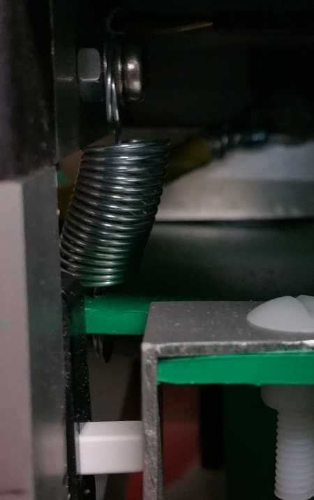
To keep a correct stifness of the spring I block head and foot of the spring with screw and bolt or by inserting in plastic, so it cannot rotate around the fixing point. This way there is no dead zone where it move freely and doesn't always come back to the same place.
BumperSpring1.jpg


BumperSpring2.jpg


To get a correct braking of the mow blades, I change the 2 single mosFet drivers for 2 full H-briges 6201P (from the shop). Now the blades are stopped in less than 2 seconds. And as predicted by Werner, it reduces the consumption ( by ~25% ). :)

I also had to modify the 24V supply cabling for the brakes to work correctly when emergency button is pushed. In fact to get an efficient bracking, the command of the driver must be kept up. So now, after the 24 V main switch I have 2 lines, one going directly to the pcb and a second one, cut by the emergency pushbutton, supplying only the 2 protection boards and from there the power side of all 4 drivers. The voltage of this 2nd line, measured after the emergency push button, is compared to the 1st line voltage. If both are not roughly equal, which mean the emergency button was pushed, the emergency stop sequence is lauched : keep enable pin high, set both dir pin and pwm pin equal (either both high or both low, depending on the direction). And after 2,5 seconds to be sure the motors are completely stopped, the enable pins are lowered. This avoids the motors to start alone if the push button is released.


EmergencyPB.jpg


The same emergency stop sequence is used if a lift-up is detected by the gyrometer or by the accelerometer.
In a garden without obstacle but small children, this sequence could also be lauched when bumpers are hit.

In the hope it can help to avoid some accident :S

Jacques
Attachment: https://forum.ardumower.de/data/media/kunena/attachments/2809/BumperSpring1.jpg/
 
Zuletzt bearbeitet von einem Moderator:
Oben