Reducing power usage & heat

tpbradley

New member
Hi all, just want say a massive thanks for this project. The information here is amazing and it's been fun hacking a Bosch Indego into an Ardumower!

I may well have set up my perimeter wrong, but I'm getting a fair amount of heat from the power resister (4.7ohms, possibly need more here) in the loop. The current pull is around 0.1 amps and the potentiometer is maybe at 50%.

Something that the Bosch mower did was send a signal for 8ms and then switch off for 92ms. I've done a little testing here to see what difference it made to the sender and using this approach brought the current down to 0.08 amps and the power resister barely warms up.

What I'm now having problems with is getting the mower to recognise the new signal, I don't fully understand the code here yet.

Has anyone tried this approach before or think it might work?

Also, instead of using current detection to know if the mower is in the station, I'm re-using the Bosch's magnetic reed sensor. It seems like a more robust solution.

Cheers
Tom
 
Hey Tom,
I hope you still remember me (you did contact me via email before regarding the Bosch Indego ;) ) - Regarding the heat, you can try to reduce voltage or increase the power resistor (http://wiki.ardumower.de/index.php?title=Perimeter_wire#Sender_power_control). The problem with the pause is that the
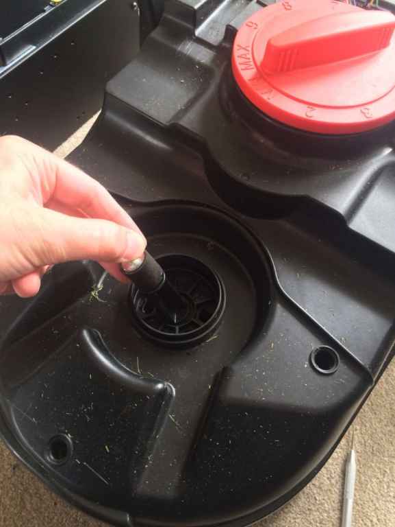
 Arduino has other things to do in parallel and so only has let's say 10ms in a second of time for processing the perimeter (matched filter). If this is during the sender switched-off-time, no signal is received. The basic principle of a matched filter is a described e.g. here: http://www.theboohers.org/playing-with-matched-filters/ http://archive.cnx.org/contents/9bb5c1f1-040c-4924-bd00-6863a0555554@5/matched-filter http://www.grauonline.de/alexwww/ardumower/filter/filter.html Regards,
Alexander
 
Hey Alexander,

Yeah sure I remember! Thanks for all your help back then. I've been able to successfully re-use the Indego's chassis, battery, motors, mower, and docking station!

And, I've discovered something that you may not be aware of. In your description of the cover hanger you say that the cover acts as a universal bumper that'll move slightly to consume impact energy and the motor current will increase. In trying to replicate this behaviour, I believe I've found that the Indego uses another method to detect impact.

The front cover mount can freely move around much like a joystick. Underneath this joystick are 4 IC's which I'm fairly certain are magnetic reed sensors. So any movement on the cover would move the front joystick and switch the reed sensors (see pics). It could be worth trying to replicate this on the Ardumower, maybe?

EDIT: Actually, I think they are linear hall effect sensor ICs with analog output. Possibly Allegro A1324. The IC's have 324 written on them.

IMG_5262.jpg

IMG_5259.jpg


I forgot to mention the voltage in my original message. I managed to get it down to 9v, any lower and the robot lost the signal in the middle of the lawn. I've not tried increasing the power resistor yet but will try this soon.

I had a feeling the robot was only looking for a signal for a short period of time, it explains the results I was seeing. I'm fairly new to Arduino/Ardumower programming (around 6 weeks) but I'm wondering if there's a way the mower could look for a signal at a specific time. Say the sender transmits for 10ms in every 100ms. The mower would initially need to listen for up to 100ms to find a signal. If a match was found between 43ms and 53ms the mower could schedule an interrupt timer to fire every 100ms looking for a signal at this point. I believe this is what the Indego does while it's displaying the "please wait whilst product synchronises" message.

Another possibility is maybe use an Arduino Nano for signal processing that could notify the main board if we have a lock on a signal. It could also operate a relay controlling power to the wheels / mower, so if the signal is lost the power is cut. I think the Indego did something like this too. When it get's a signal lock you can hear a relay switching.

Cheers
Tom
Attachment: https://forum.ardumower.de/data/media/kunena/attachments/4130/IMG_5259.jpg/
 
Zuletzt bearbeitet von einem Moderator:
The 4 reed sensors (north, west, east, south) is really something new you found out, excellent! I took the freedom to add your photo to my Indego page (hope it's ok).
We should consider this idea when designing a new Ardumower chassis (current chassis is this one: https://github.com/Ardumower/ardumower/tree/master/cad/ardumower_chassis_0_99). https://github.com/Ardumower/ardumower/blob/master/cad/ardumower_chassis_0_99/picture.jpg

There's the idea (and a prototype) to CNC make the chassis out of fiberboard, this is more environmental and would be a major difference to others. We are open to ideas how to implement this bumper idea with it.

Regarding the synchronization of sender and receiver, I can try it, I think it could work. Thanks for your suggestion! This and future optimizations will be done for the Arduino Due in the Sunray firmware (https://github.com/Ardumower/Sunray) , for example storing the ADC conversions is now performed completely-off the core processing unit by the DMA controller in the Arduino Due. And we are working on sensor fusion (odometry, compass, perimeter) based localization code, so the user will see on a map where the mower currently is (http://www.ardumower.de/index.php/de/forum/software/827-ardumower-software-sunray?start=80#11917). All this needs some more working memory and can only be done with the Arduino Due...
 
nero76 schrieb:
The 4 reed sensors (north, west, east, south) is really something new you found out, excellent! I took the freedom to add your photo to my Indego page (hope it's ok).

Of course! I'll let you know if I come up with any ideas on implementation.

I've been keeping an eye on the Sunray firmware.. it's looking seriously good! Quick question, can I just swap the Mega for a Due? I have v1.2 of the main board and would love to have a play with this new stuff ;)
 
Zuletzt bearbeitet von einem Moderator:
It would be great if synchronization did work, it could mean the sender uses a tenth of the power. And we could increase the signal strength for larger perimeters wires!
 
Yes, we should try it, no doubt. Regarding Sunray, it's still heavy experimental. I'll make a new wiki page for Sunray and describe how to start with it (compass calibration, Arduino Due adjustments for PCB 1.2). The goal is to use PCB 1.3 for it.
 
Oh man, this is awesome!

I have a few questions before I dive on in ;)

1. Can I run the Azurit firmware on the Arduino Due with the PCB1.2 mods for 3.3v?

2. The compass tower is interesting! I've had quite a few problems calibrating the compass myself and only just discovered my original Bosch didn't have one! Any thoughts on how it would have achieved lane by lane mowing without a compass? (Maybe is used the GPS?)

3. How do I run the PC software? I have a Mac which I'd prefer to use but could find a Windows machine. Is the processing_sunray program written in Java?

4. Unrelated to Sunray, I'm having quite a few issues with Power. My battery is hacked from the old Bosch and runs at 32v so I've added two LM2596 modules to drop the voltage going to each of the motor protector boards. This seems to be working fine, but I'm worried about the high charge voltage passing through the 24v relay. Would you recommend adding a resistor at R19 and are there any other changes you'd make for a higher voltage system?

Cheers
Tom
 
Hi Tom,

1. Yes, latest Azurit now runs on PCB1.3 as well and that means it supports Arduino Due and 3.3v (for PCB 1.2 you need the mods, however highly recommended is PCB1.3)
2. I cannot believe it works without compass. The gyro alone will drift over time. There must be some precise direction sensor to keep the exact lane (and to be exactly on the next one). GPS direction wouldn't be precise enough. To be within 0.1 meter error over 10 meters, you would need a 0.5 degree precise direction (yaw error=arcsin(0.1m/10m) = 0.5 degree). That's really difficult even with a compass... Maybe the compass was on the Bosch main PCB in the first versions?
3. You need Processing: https://processing.org/download/ (I'll add it to the wiki)
4. So you are running the motors at 24v only? I'll have to ask Uwe or Jürgen regarding recommended changes for a 32v system.

Regards,
Alexander
 
Hey Alexander, thanks for cleaning this up for me!

1. Awesome, I'll grab a Due and have a play ;)

2. I've examined the Bosch main board more closely and can't find anything that looks like a compass. I wonder if it's possible to use a single GPS for direction and relative positioning? I can't think why Bosch would have included a GPS in the original Indego and removed it in the 'Connect' version. The mower doesn't need to know it's precise position in the world, only relative to the perimeter. So I wonder if a single GPS is accurate enough for this purpose?

4. The Bosch motors are rated around 36v but the Pololu drivers can only handle 28v so I've reduced the voltage to around 27v. Bosch were already under powering the motors with a 32v battery.

Cheers
Tom
 
At a closer look (down to 2 meters), GPS is a very noisy positioning, and it's noisy in all directions. You could try some clever filtering (e.g. Kalman filter) but I assume you will have to regularly track the perimeter as this only will give you some precise direction combined with the GPS and filter? And if I remember correctly, the old Bosch did track the perimeter much more often than the Connect.
 
Yes you're right, all of a sudden the mower would wonder off and track the perimeter for a while, then start mowing again lol

I forgot to ask earlier, what should the current be on the perimeter sender? I've seen "No more than 1 amp" mentioned, but I've managed to get mine down to 0.15 amp. Any higher than this and the power resistor becomes really hot. I've had to drop the "Timed-out if below smag" in the mower to around 10 to make this work. Is there a reason the default smag is 300?
 
The default smag of 300 is because the perimeter receiver coils in the Ardumower chassis are very close to the motors, and anything below 300 is just due to noise of the motors. Can you try to set the potentiometer to 100% (so no PWM of the signal)? A PWM on the signal will make the smag more worse. It's normal that the power resistor gets hot, and you typically at a heat dissipation to it (example: https://qph.ec.quoracdn.net/main-qimg-7d2f62faf0ef3426a977f2f9e8b0c284-c).
 
Ah yes that makes sense! It's a pretty groggy day here today so I'll keep fiddling with it throughout the week :D
 
hey tpbradly, did you successfully got the indego working with the ardumower pcb? i am interested in doing the same as the mainboard of my bosch indego 1000 is broken.... regards, martin
 
Hey Martin, I did indeed! I have the original bosch indego (2013 model) which died just after 3 years. Replaced the PCB with the ardumower PCB and it's up and running again. I had to remove a couple of cells from the battery because the voltage was too high. Apart from that all went fairly well. I'm now running v1.3 of the PCB with an Arduino Due and Raindancer firmware.
 
Oben