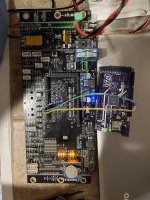
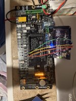
Checked pin headers and loaded the sleep with no luck. I was going through the diagrams of the circuits and couldn’t quite find the 3v circuit powered by the arduino. It must be something downstream of the arduino is my only guess now. I can smell and feel that it is generating heat somewhere but cannot isolate it.
Du verwendest einen veralteten Browser. Es ist möglich, dass diese oder andere Websites nicht korrekt angezeigt werden.
Du solltest ein Upgrade durchführen oder einen alternativen Browser verwenden.
Du solltest ein Upgrade durchführen oder einen alternativen Browser verwenden.
PCB keeps 'booting'
- Ersteller K!NG
- Erstellt am
Hi @mfethe,
Sorry for the late reply.
Thanks for doing this analysis. Good Job! Via this you are getting close. The conclusion so far: Your Arduino Dues 3.3V supply gets overloaded which is caused by the Ardumower mainboard. It's or the header/pin -interface or a something else on the mainboard.
I guess somwhere a bad soldering / short circuit resulting in a overrload of the 3,3V.
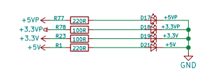
So far as I can see in the drawings, the mainboard is not using the 3,3V coming from the Arduino. It's only used for the LED indicator [D19] labeled as "+3,3V":
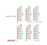
And the 3,3V is wired towards pin header [P34] (for dev purpose I guess)
As a very quick workaround. Why not bending the 3,3V pin coming from the Arduino ? Via this you isolate the 3,3V as it will not make any connection with the Mainboard and the complete solution will remain stable which allows you to continue with your build. During the time you continue with the build you will find out soon the root cause...
Sorry for the late reply.
Thanks for doing this analysis. Good Job! Via this you are getting close. The conclusion so far: Your Arduino Dues 3.3V supply gets overloaded which is caused by the Ardumower mainboard. It's or the header/pin -interface or a something else on the mainboard.
I guess somwhere a bad soldering / short circuit resulting in a overrload of the 3,3V.
So far as I can see in the drawings, the mainboard is not using the 3,3V coming from the Arduino. It's only used for the LED indicator [D19] labeled as "+3,3V":

And the 3,3V is wired towards pin header [P34] (for dev purpose I guess)

As a very quick workaround. Why not bending the 3,3V pin coming from the Arduino ? Via this you isolate the 3,3V as it will not make any connection with the Mainboard and the complete solution will remain stable which allows you to continue with your build. During the time you continue with the build you will find out soon the root cause...
Like I said it appears some of the U (U3 & U15) transistors for the Wi-Fi and Bluetooth are fried. Not sure if I can replace the small parts on the board but I’m going to give it a try once I receive those components. I was able to remove them but it looks like one pad on each could be bad. Any tips on this? 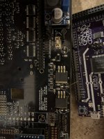

Also there is no connectivity on the fried pad to any of the 3v pins or the arduino. So I think this is definitive on the cause of the problem. My next question would be is it possible to attach the Wi-Fi and Bluetooth modules through an another I2C connection that is not currently used. If that’s possible I believe it would be an easier and more sustainable fix. @W1976 is this possible?
Also another thing that it happening now with u3 and u15 remove is the orange light on the arduino no longer flashes and I get nothing from the serial output. I must have been mistaken and there maybe another issue. Can anyone confirm what is driving the TX light from the arduino? This light comes on when powered by usb but not by battery through the board.
