PCB 1.3 Shield dips soldering fail

markor

Member
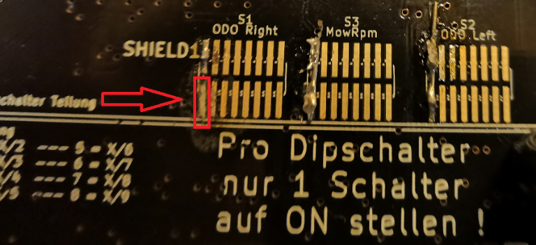
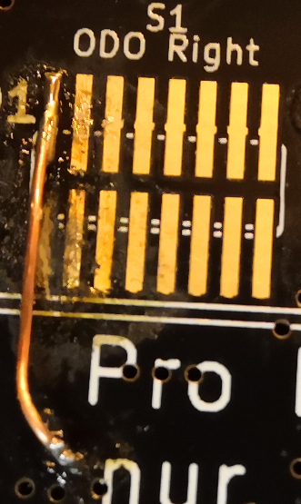
I'm putting up my second unit now and I just made a total mess of the dips soldering. S2 and S3 are ok, but while soldering the S1 I managed to connect adjacent pins and while desoldering and resoldering the lower pin contact eventually came totally off. The pin I'm talking is the one inside the red box in the picture, there really is nothing but motherboard plastic left even if it looks there is the contact still.

shieldDips.png


So what are my options:
1. Can I do a jump wire somewhere? If so, how? I was looking at schematics, but couldn't really figure out what mapped to what on the chips on otherside of pcb.

2. Or should I just try remove all the solderings and use the 3rd pins? It says it's x/4 divider, but what does that really mean? Can it be easily changed within the code? Should I use the x/4 only for drive motors or for the mower motor too? The only thing I can find in the code is the below. I'm afraid there might be something else hardcoded around..

Code:
#define DIVIDER_DIP_SWITCH  2             //  sets used PCB odometry divider (2=DIV/2, 4=DIV/4, 8=DIV/8, etc.) 
odometryTicksPerRevolution /= DIVIDER_DIP_SWITCH;        // encoder ticks per one full resolution


3. What else?
 
You can also try to scratching the track, and solder there the wire. Take hot glue then to fix the wire after soldering. I would use a microscope for this.
Or you can solder a cable from the upper pad to the throughhole (if it has contact) or pad where the track comes from (see schematic). Maybe you need also a microscope because
this is a smd part.
 
Are you sure you need ODOMETRY
If you use azurit without slope on your area ,the odometry is not necessary
So maybe you can also leave it like that and don t connect the motor codeur wire.
 
Roland schrieb:
You can also try to scratching the track, and solder there the wire. Take hot glue then to fix the wire after soldering. I would use a microscope for this.
Or you can solder a cable from the upper pad to the throughhole (if it has contact) or pad where the track comes from (see schematic). Maybe you need also a microscope because
this is a smd part.

Thanks for the tip. It seems the through hole does have contact, so I might try that. Only microscope I have is my honor 10 with 10x which actually works surprisingly well..

However I have been going through the schematics and this forum for hours. Looking at the PCB there is a counter chip HEF4017BT between the odometry connectors P8, P9 and Arduino due. The 4017 chip is a counter chip, which will limit the odometry ticks that get through to DUE. 4017 takes in ticks from odometry and only sends the signal forward when certain count of incoming ticks have arrived. If the motor's odometry sends 800 ticks per revolution and the 1:2 (first "pin") has been connected for 4017, it will only send 400 ticks to DUE. If you connect the 3rd "pin" it will only forward every 4th tick which makes it to 200 per revolution. What I read from forums is that this was required for boards before due and now DUE could easily handle all incoming ticks without any divider in between.

After reading schematics I should be able to connect the odometry connectors directly to DUE pins like: odo right connector p8.3 to DUE AD14 and odo left connector p9.3 to DUE AD12. This would give me 1:1 ticks from odo to DUE, this would also make the odo function more precise with more ticks? Am I missing something, can this be done?
 
Zuletzt bearbeitet von einem Moderator:
Your OK for 4017 and DUE vs Mega.
But Be carrefull
: odo right connector p8.3 to DUE AD14 and odo left connector p9.3 to DUE AD12
Never send more than 3.3V on AD12 or AD14 with a DUE on PCB1.3
You can test in by Simply Power the motor odometry only at 3.3V to be sure and test it.
 
After reading schematics I should be able to connect the odometry connectors directly to DUE pins like: odo right connector p8.3 to DUE AD14 and odo left connector p9.3 to DUE AD12. This would give me 1:1 ticks from odo to DUE, this would also make the odo function more precise with more ticks?
Not really. The ODO gives back a 5V Signal. The DUE works with 3.3V. You have to cut ODO pin 3 from the track and then connect it to 5V_IN of the LSchifter10/9 and remove the track from Odoteiler->Ausgang1/2 to LSchifter10/9 or the AND gate.
 
Roland schrieb:
Or you can solder a cable from the upper pad to the throughhole (if it has contact)

Thanks, that was my first choise to try and I think I did pretty ok with it. I will know when I test the odometrics. If this didn't work my second play will be to try the 1:4 (third "pins") for the drive motors. It seems there's no odo in the current mower motor in the starter kit, so It can be whatever.. Third option will be to mod the PCB to feed the motor odo's with 3,3v and go straigth from p8.3/P9.3 to DUE AD12/AD14 for the full 1:1 ticks.

odoright.png


Bernard schrieb:
Your OK for 4017 and DUE vs Mega.
But Be carrefull
Never send more than 3.3V on AD12 or AD14 with a DUE on PCB1.3
You can test in by Simply Power the motor odometry only at 3.3V to be sure and test it.

Thanks that could be a lifesaver, if I choose to try it as the odo slot seems to be 5v on default.

Bernard schrieb:
Are you sure you need ODOMETRY

Yes, the area that I'm doing with these two is big and has lots of slopes. Going to be doing some extra coding for it and once I get the working IMU's, I need to better the preformance with the compass also.
Attachment: https://forum.ardumower.de/data/media/kunena/attachments/4985/odoright.png/
 
Zuletzt bearbeitet von einem Moderator:
Roland schrieb:
After reading schematics I should be able to connect the odometry connectors directly to DUE pins like: odo right connector p8.3 to DUE AD14 and odo left connector p9.3 to DUE AD12. This would give me 1:1 ticks from odo to DUE, this would also make the odo function more precise with more ticks?
Not really. The ODO gives back a 5V Signal. The DUE works with 3.3V. You have to cut ODO pin 3 from the track and then connect it to 5V_IN of the LSchifter10/9 and remove the track from Odoteiler->Ausgang1/2 to LSchifter10/9 or the AND gate.

Thanks, will look into this if the need demands. I think it's easy to test first if the odometry gives out the required 3,3v if I send in 3,3v instead of 5v to motor's odometrie. If that doesn't work and the other backup plans before that... ;)
 
Zuletzt bearbeitet von einem Moderator:
If the odo can work at 3.3v you can also use reserve Ad13 and Ad15 and change the code according (it is bit adressing so little more complex)
In the past there are used for channel B of the encoder.
 
MarkoR schrieb:
Roland schrieb:
Or you can solder a cable from the upper pad to the throughhole (if it has contact)

Thanks, that was my first choise to try and I think I did pretty ok with it. I will know when I test the odometrics. If this didn't work my second play will be to try the 1:4 (third "pins") for the drive motors. It seems there's no odo in the current mower motor in the starter kit, so It can be whatever.. Third option will be to mod the PCB to feed the motor odo's with 3,3v and go straigth from p8.3/P9.3 to DUE AD12/AD14 for the full 1:1 ticks.

odoright.png

Happy to inform everyone that this bridge is working great and getting good odometries from both wheels! :)
 
Zuletzt bearbeitet von einem Moderator:
Oben