Odometry not working

xmonika

New member
Hello, I just build my first Ardumower PCB1.3. First big thanks to everyone contributing to this excelent open source project.
I am doing Azurit prescribed tests and have problem with odometry, which doesnt generate any impluses in my guess. I have bought everything from marotronics shop. First problem was that the engine has 4pin conector for pulse hall sensor counter. Onboard P8 and P9 is only 3 PIN. So I have connected red-brown, black-green, yellow-blue (output) and omitted purple on motor side.
IMG_20180515_102040.jpg


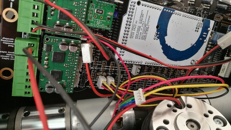
Motor test is working okay, but the odometry test (2 in console) has empty output which (I guess) is related to no impulse receiving.
IMG_20180515_131734.jpg


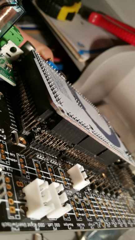
If I start the mottor and put voltmeter to data PIN of P8/P9, it shows 2,5V which I guess means the motor is generating impulses.
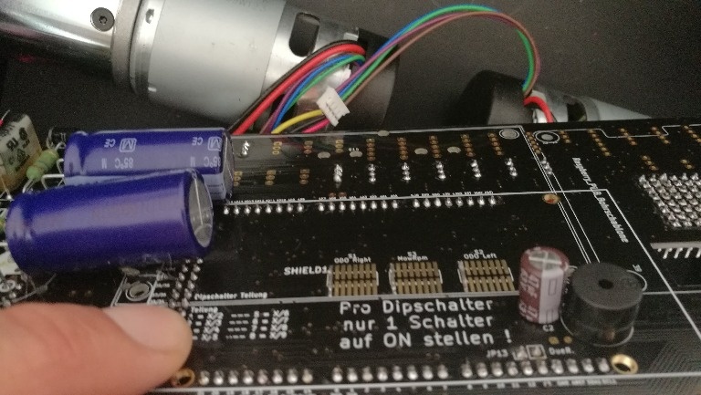
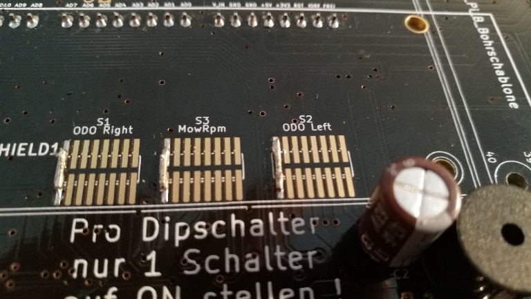
If I put the voltmeter on the output of U4/U9 in the ODO S1 botom PCB area it shows 0

Is the wirring okay?
Did anybody had simillar issue in the past?
Does anybody have idea what else to check?

Thank you
 
Hi.
Have you enabled the Odometry into arduremote (or in mower.cpp if you don't use Bluetooth)?
I think the Wiring is OK.
By.
 
Yes, i didn't changed it from the downloaded source. There is
odometryUse = 1; // use odometry?

I thought that I forgot something very basic or simple but it may be more complicated.
 
Hello,

I think you did everything correct. Can verify you get correct signals at all P8/P9 pins. Please measure voltages between GND (black) and...
VCC (red)- should be 5v
SIGNAL (yellow)- should alternate between 0v and 5v when the motor rotates

If you only get 2.5V on the signal lines, the pull-up resistors on the Arduino Mega may not be high enough - on the PCB, try to solder a 4.7K resistor between signal and VCC to get a higher signal. I think most of us use the Arduino Due, and that's another story...

Please let us know if you could solve this problem.

Regards,
Alexander
 
Hello,
thank you for the tip. I did a few measurements and experiments:
- red line is on 5V
- signal line is on 0V and on 2,51V when motor rotates (independently on speed)

The 4k7 pull up resistor didn't produced any result. Nor the 1k one. I then tried to unplug motor encoder wires and put a 100R resistor between GND and signal to simulate a few impulses, then between VCC and signal, In any case the odometry test consule input remained blank (with wheels rotating). I did this on the PCB to eliminate any wiring troubles.

I guess it should work like that: if the encoder generates a few impulses there should be a new line in console odometry test, right?
 
Can you verify the Arduino pins are working by uploading the short test code below? The code will output the state of the digital pins (0 for LOW, 1 for HIGH) in the serial console (19200 baud). After uploading the code, connect one signal pin to HIGH (5v) and LOW (GND) and see if that works.


Code:
#define pinOdometryLeft A12      // left odometry sensor
#define pinOdometryRight A14     // right odometry sensor 


int stateL = 0;
int stateR = 0;

void setup(){
  Serial.begin(19200);
  Serial.println("START");
  pinMode(pinOdometryLeft, INPUT);  
  pinMode(pinOdometryRight, INPUT);  
}

void loop(){
  int v = digitalRead(pinOdometryLeft);
  if (v != stateL){
    stateL = v;
    Serial.print("left:");
    Serial.println(v);
  }
  v = digitalRead(pinOdometryRight);
  if (v != stateR){
    stateR = v;
    Serial.print("right:");
    Serial.println(v);
  }
  delay(1);
}
 
I forgot to mention: because there is a divider for the odometry pins in between on the PCB, I think one has to make at least two transitions (HIGH,LOW,HIGH,LOW) for a signal change...
 
Just the START text.
I also did another thing - build the counter with some spare arduino and connected it to motor encoder and it worked fine. The problem seems to be somewhere in PCB.
 
Yes I know about the divider.
Voltmeter on Dipschalter S1/S2 (the wire soldered on bottom side) shows 0V independently on impulses on signal line....
 
Yes, the 5V and 5VP (and every other in the jumper rows) corresponds.
I don't have C9 implemented, nor P51 IOREF jumper nor JP13 - hope that setup is correct for 2560.
 
Maybe one workaround (if you can't find the reason): at PCB back side, connect a cable from odometry signal (yellow) to Ardunio pins A12, A14...
 
I have it!

The reason was totaly stupid and therefore I am stupid as well. I started with the proposed workaround and it didn't worked on the PCB but it worked only on the arduino directly. This makes no logic so I started to investigate and finaly found the culprit.

IMG_20180517_211025.jpg


It is almost invisible but the males are not in the females socket. I just took the arduino out three times and put it back and repeated this error everytime. Now it works like a charm. I feel a bit ashamed for using powerful resources on this thing and will think about how to remedy.

Thank you all for your help.
Attachment: https://forum.ardumower.de/data/media/kunena/attachments/4550/IMG_20180517_211025.jpg/
 
Zuletzt bearbeitet von einem Moderator:
Oben