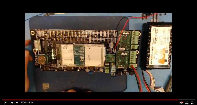
First tests of PCB 1.3 (as shown in video 7)
- Insert the fuse 1.6AT (for the time being) into fuse holder EF2.
- Insert the DC / DC converter
- Do not connect JP1
- Connect JP8 to Dauer-ON
- Connect the connection cable for the Start-Button and bridge the wire ends
(to connect)
- Connecting the Battery with P43 (Watch + and -)
- Measure tension
- Reduce voltage to 9V on DC / DC
- Battery control LED (+ 24V) must be on
- Connect JP1
- Control LEDs "+ 5VP" and "+ 3.3Vp" must light up
- Disconnect the battery and remove the measuring device
- Bridge the NOT-AUS connection with a wire bridge
- Reattach the battery
- Control LEDs "Dual1" and "Dual2" must light up
- Disconnect the battery again
- Connect motor drivers
- Reattach the battery
- All Control LEDs light up as before
- Disconnect the battery again
- Mount Arduino (JP13 for Marotronics DUE (clone))
- Reattach the battery
- LEDs "+ 3.3V" and "+ 5V" now light up (all control LEDs are on) and Buzzer beeps
continuously
- Disconnect the battery again
- Move fuse from 1.6AT to EF1 and insert fuse 5AT into EF2
- Insert INA, relay and RTC
- Reattach the battery
- Finally, place the Bargraph (choose the right direction)
- First LED (Station LED) and last LED (Buzzer) Burn and Buzzer beeps continuously
(On the video, the 4th LED flashes, apparently by the "BLINK" program on the
DUE, this was
Not so with me, despite the blinking program focused on pin13 from Arduino ... ???)
! Oh yes, I have not soldered the wire bridges for the dividers yet, I'd like to study odometry first ...
Or is that a problem to continue?