Connection of GPS

petelake

New member
Hello,

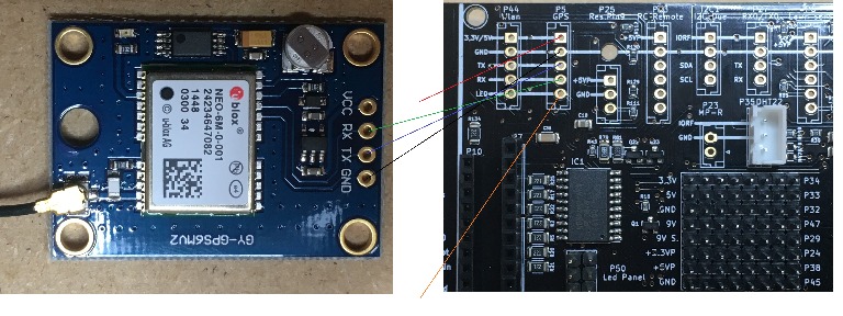
Can someone tell me how the GPS module is connected correctly?
See the attached photo ...
GND to GND, Rx to Rx and TX to Tx seems obvious.
I take 3.3V / 5V to VCC (JP7 at 5V), right?
But, where should the wire go from "LED"? (orange)

Probably JP12 should also be set to 3.3V, right?

Thanks in advance

connectieGPS_2018-02-21.jpg
 
Hi Pete.
2 Years ago i connect the GPS to the PCB1.2 but the result was :
It's difficult to manage a GPS with an arduino, and actualy AZURIT read the value but don't use a lot(except to detect if stuck if i remember so you need to dev your own feature like other member to manage area for example.)
I think it's better to use the power of a Raspberry PI and a Neo M8N(more precise) for this kind of module.

I never connect the GPS to the PCB 1.3, so need to confirm but:
GND to GND, Rx to Rx and TX to Tx seems obvious.
I think you are OK because when you look at Kicad Page 8 the RX are TX are already crossover.
I suppose you want to use an Arduino DUE.
For the voltage, The Shop module can work from 3 to 5V so normaly no problem with the DUE and set JP7 and JP12 to 3.3V
For the Led you don't use this feature with the shop module and it's connect directly on the board led.

By.
 
Oben