Hi,
Anyone has an idea (if it is possible at all) how to properly connect two mow motors (from the shop) to the PCB 1.3 on 3d printer chassis (aka V2)?
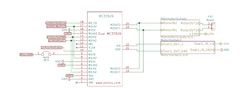
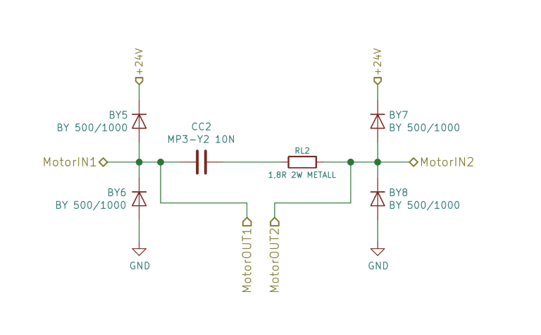
Original (V1) chassis has 1 mower motor and it is attached via motor protection circuit to both outputs of MC33926.
At the same time it measures current (via one of the channels) and check for the faults reported by controller.
What would be the approach to connect two mower motors to PCB 1.3?
Option 1: Connecting both mower motors in parallel via P37?
Potentially, MC33926 can supply just enough current as the motor uses ~2.7A and the controller supports 3A/channel (based on https://www.pololu.com/product/1213 ).
As driver has "under-voltage, over-current, and over-temperature protection", probably it wouldn't burn down immediately.
However, I guess that there's purpose why one motor was connected to two channels with one motor setup")
Sensing with two motors would be off and not represent actual situation (e.g. mower turns mowing engine off if the power consumption is above 75W for certain time, which wouldn't make sense with 2 motors). Without sensing, it is basically an option 2, with barely capable controller.
Option 2: Using powerful enough controller (or controllers) and go without the feedback
That would be similar to using LM298-type controller. Some intermediate board might be nice.
Little software modification would be required, to drop the checks for the mow motor, but leave for the drive motors, but in general it should work.
Any other options?
Thanks,
Romualdas
Anyone has an idea (if it is possible at all) how to properly connect two mow motors (from the shop) to the PCB 1.3 on 3d printer chassis (aka V2)?
Original (V1) chassis has 1 mower motor and it is attached via motor protection circuit to both outputs of MC33926.
At the same time it measures current (via one of the channels) and check for the faults reported by controller.
What would be the approach to connect two mower motors to PCB 1.3?
Option 1: Connecting both mower motors in parallel via P37?
Potentially, MC33926 can supply just enough current as the motor uses ~2.7A and the controller supports 3A/channel (based on https://www.pololu.com/product/1213 ).
As driver has "under-voltage, over-current, and over-temperature protection", probably it wouldn't burn down immediately.
However, I guess that there's purpose why one motor was connected to two channels with one motor setup
Sensing with two motors would be off and not represent actual situation (e.g. mower turns mowing engine off if the power consumption is above 75W for certain time, which wouldn't make sense with 2 motors). Without sensing, it is basically an option 2, with barely capable controller.
Option 2: Using powerful enough controller (or controllers) and go without the feedback
That would be similar to using LM298-type controller. Some intermediate board might be nice.
Little software modification would be required, to drop the checks for the mow motor, but leave for the drive motors, but in general it should work.
Any other options?
Thanks,
Romualdas