Du verwendest einen veralteten Browser. Es ist möglich, dass diese oder andere Websites nicht korrekt angezeigt werden.
Du solltest ein Upgrade durchführen oder einen alternativen Browser verwenden.
Du solltest ein Upgrade durchführen oder einen alternativen Browser verwenden.
bumpers
- Ersteller gjmoule
- Erstellt am
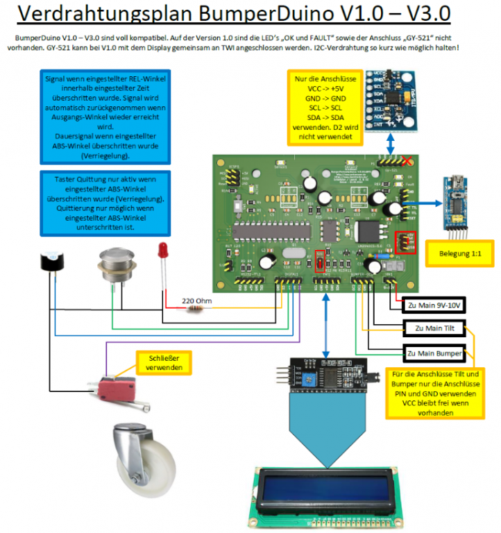
Jürgen engineered an excellent pressure-based universal bumper sensor for the Ardumower complete with PCB, schematics, instruction manual, videos (kit is ready for shopping ). The sensor's sensitivity can be set individually.
It's called the 'BumperDuino' and you can find more information on the Wiki now:
http://wiki.ardumower.de/index.php?title=Bumper_sensor
It's called the 'BumperDuino' and you can find more information on the Wiki now:
http://wiki.ardumower.de/index.php?title=Bumper_sensor
Hi,
from my point of view is bumper still a weak point, because no general solution.
I spent a lot of time to develop bumper with sensitivity adjustment and also which will not move touched object ( must have a over run ). Now I'm testing last version. If will work correct, I will present.
Alex
from my point of view is bumper still a weak point, because no general solution.
I spent a lot of time to develop bumper with sensitivity adjustment and also which will not move touched object ( must have a over run ). Now I'm testing last version. If will work correct, I will present.
Alex
Hello
From a safety point of view, the weakness of the pressure sensor is that it only senses on a narrow band at a fixed height which will not always be the right one to detect the small foot of a chid or the fur of an animal. I think that commercial mowers with full body as bumper are safer. Furthermore, as pointed by Alex, a long overrun allows the mower to slow down, if not completely stops, before really pushing with full pressure. On that point too, the pressure sensor, from what I understand of its presentation, might not be the safest solution.
Large, envelopping bumpers with hall sensors that allow longer overrun than switches, still have some future")
Jacques
From a safety point of view, the weakness of the pressure sensor is that it only senses on a narrow band at a fixed height which will not always be the right one to detect the small foot of a chid or the fur of an animal. I think that commercial mowers with full body as bumper are safer. Furthermore, as pointed by Alex, a long overrun allows the mower to slow down, if not completely stops, before really pushing with full pressure. On that point too, the pressure sensor, from what I understand of its presentation, might not be the safest solution.
Large, envelopping bumpers with hall sensors that allow longer overrun than switches, still have some future
Jacques
max@birley_com
Member
I have just completed the build of the Bumperduino.
I connected the FTDI/usb module to the BumperDuino using all 6 pins . The jumper is connecter to VUSB and I get one green LED
When I come to upload the code I get sync errors reported in the IDE.
Question when the ATMEGA328P-PU chips are purchased from the Ardumower shop is the boot loader burnt onto the chip already or must I do this Or is there another reason why I can not upload to the chip.
When I place the chip in the ic holder it was a little difficult to align all the pins. They do all seem to be in correctly. Is the chip sensitive to static?
Also I have the PCB 1.3 and the bumper connection at P11 has 4 connections
Starting at the outmost pin moving inwards the pins
pin 1 is connected to pin2 so they are ground
pin 3 and 4 read 3.28v
Not sure how this relates to DC 1 and DC2
Question is how do I connect the BumperDuino to the PCB 1.3?
Also where is the 9-12v coming from on the PCB 1.3 to power the BumperDuini? VIN + & -
regards
Max
max@birley_com
Member
I just read in the shop that the boot loader is already on the chip.
Question does the board need to be externally powered by 9-12 volts @Vin in addition to the 5 volts supplied by the FTDI with uploading?
Question does the board need to be externally powered by 9-12 volts @Vin in addition to the 5 volts supplied by the FTDI with uploading?
max@birley_com
Member
ok just fixed the issue
I had crossed tx rx on the FTDI
when I connected tx to tx and rx to rx it uploaded
the code that works for me only contained the bumperduino code and not the sound
Still not sure how to connect this to the 1.3 PCB board
I had crossed tx rx on the FTDI
when I connected tx to tx and rx to rx it uploaded
the code that works for me only contained the bumperduino code and not the sound
Still not sure how to connect this to the 1.3 PCB board
kurzschuss
Administrator
Zuletzt bearbeitet von einem Moderator:
kurzschuss
Administrator
Zuletzt bearbeitet von einem Moderator:
max@birley_com
Member
Hi
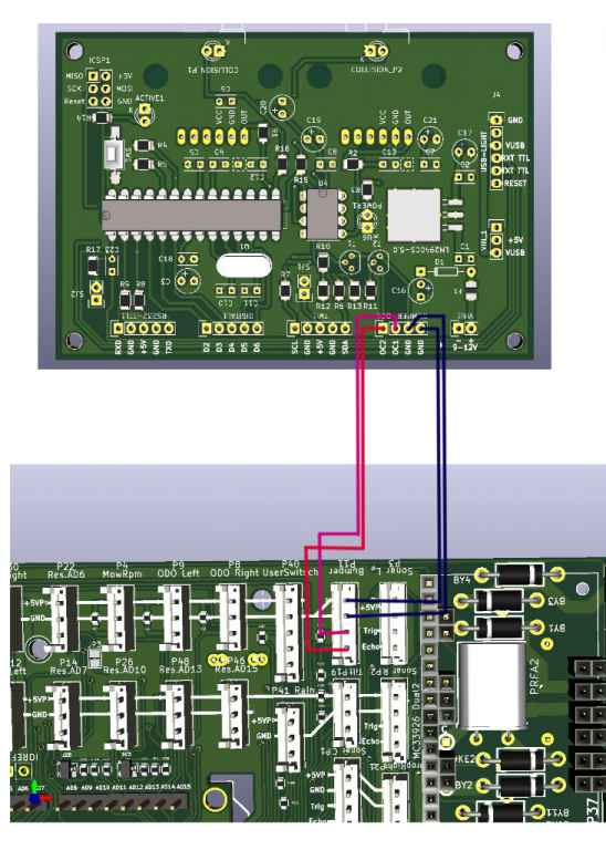
The diagram is now very clear. Regarding the power there is a square area on the pcb that has many pins. Rows for gnd, for 5v 3.3 volts and 9volts. I think I need to power the bumperduino from the 9volt from these pins. Other suggestion?
Also when powering not via the ftdi then the jumper need to be move to Vin ie away from VUSB
If I separate the bumper into 2 separate pressure pipes does having 2 separate pressures effect the code ie if the left pressure pipe is triggered the mower turns right and so on?
Thank for your help
Max