Brushless Driver Board with BL8015 Problem

Manu27

Member
Hi,

Ì would like to check my test before to join the shop.

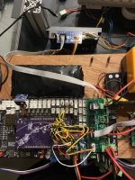
I have a brushless board with the BL8015 drivers. Right and mower motors works fine. The Left motor doesn't.
If I'm switching the cable of the left and the right. The opposite happens: the left works fine and the right doesn't.

with an oscilloscope, I've checked the signals . the pinMotorLeftPWM and Dir looks good. But the out signals of the brushless board still to 0V

Do you see other test that I can do ?

thanks a lot
 
have a look to pin2 Enable, this shoulg be low and Pin 5 Brake, aslo Low.
Please send a photo of you board and cabling.
 
Zuletzt bearbeitet:
Hi thanks for your reply.

I did a video :

On the working motor (the first one on the video)
Pin 1 (GND) : 0v
Pin 2 (ALM) : 3,3v
Pin 3 SPEED : signal
Pin 4 AVI : 3,3v
Pin 5 BRK : 3,3v
Pin 6 ENBL : 0
Pin 7 F/R : 3,3 v

On the non working motor (the second on the video)
Pin 1 (GND) : 0v
Pin 2 (ALM) : 3,3v
Pin 3 SPEED : 0v
Pin 4 AVI : 0v
Pin 5 BRK : 3,3v
Pin 6 ENBL : 0v
Pin 7 F/R : 0 v

If I swap the cable (flat cable) the working motor (the first one) is no more working, and the non working motor (the second) is working
 

Anhänge

  • IMG_9016 Moyenne.jpeg
    IMG_9016 Moyenne.jpeg
    113,2 KB · Aufrufe: 18
  • IMG_9017 Moyenne.jpeg
    IMG_9017 Moyenne.jpeg
    108,5 KB · Aufrufe: 19
Hello;
sorry for the late answer, but I was on a business tripp.
Regarding the Pins:

On the non working motor (the second on the video)
Pin 1 (GND) : 0v
Pin 2 (ALM) : 3,3v ok, Alarm is low activ
Pin 3 SPEED : 0v this is an output and indicates the motor speed, if the motor does not spin, low is ok
Pin 4 AVI : 0v here you should see the PWM signal, low indicates no spinning.
Pin 5 BRK : 3,3v ok, Brake is low activ
Pin 6 ENBL : 0v ok, Enable is low activ
Pin 7 F/R : 0 v ok, this indicates the direction, if one motor is high, then this should be low.

Please check PWM Signal at PIn 14 of eacht plug
1684082026548.png
 
hello ,

thanks a lot for the explanation of the motors pins.

i've checked the PIN for the PWM signal

But, from my point of view, the second pin 14 (on the right) match with the pinMotorMowPWM ? no ? I've double checked on the schema. And the Pin 5 matches with the second motor

Then I have

1st 18 pins connector:
pin 5: the PWM signal of one motor
pin 14: the PWM signal of the second motor

2nd 18 pins connector:
pin14: 0v if the mow is off, else PWM signal

due to that I guess something is wrong on the board
 
for information, I've ordered a second board. And with this new one, no problem. Everything is working fine.
so the first one has a problem
 
Oben